SAM-M8Q - Hardware Integration Manual
UBX-16018358 - R05 Production Information Design
Page 9 of 23
2 Design
2.1 Pin description
Provide clean and stable supply (low impedance, < 0.2 Ohms).
1, 4, 5, 6,
10, 11, 15,
16, 20
Assure a good GND connection to all GND pins of the module.
IO supply voltage. Must be always supplied. Usually connect to
VCC Pin 17
It is recommended to connect a backup supply voltage to V_BCKP
in order to enable Warm- and Hot Start features on the positioning
module. Otherwise, connect to VCC_IO.
Can be configured as TX_Ready for DDC interface. Leave open if
not used.
Leave open if not used. Do not drive high. Do not connect a
capacitor at this pin.
Configurable Timepulse signal (one pulse per second by default).
Leave open if not used.
Table 1: SAM-M8Q Pinout
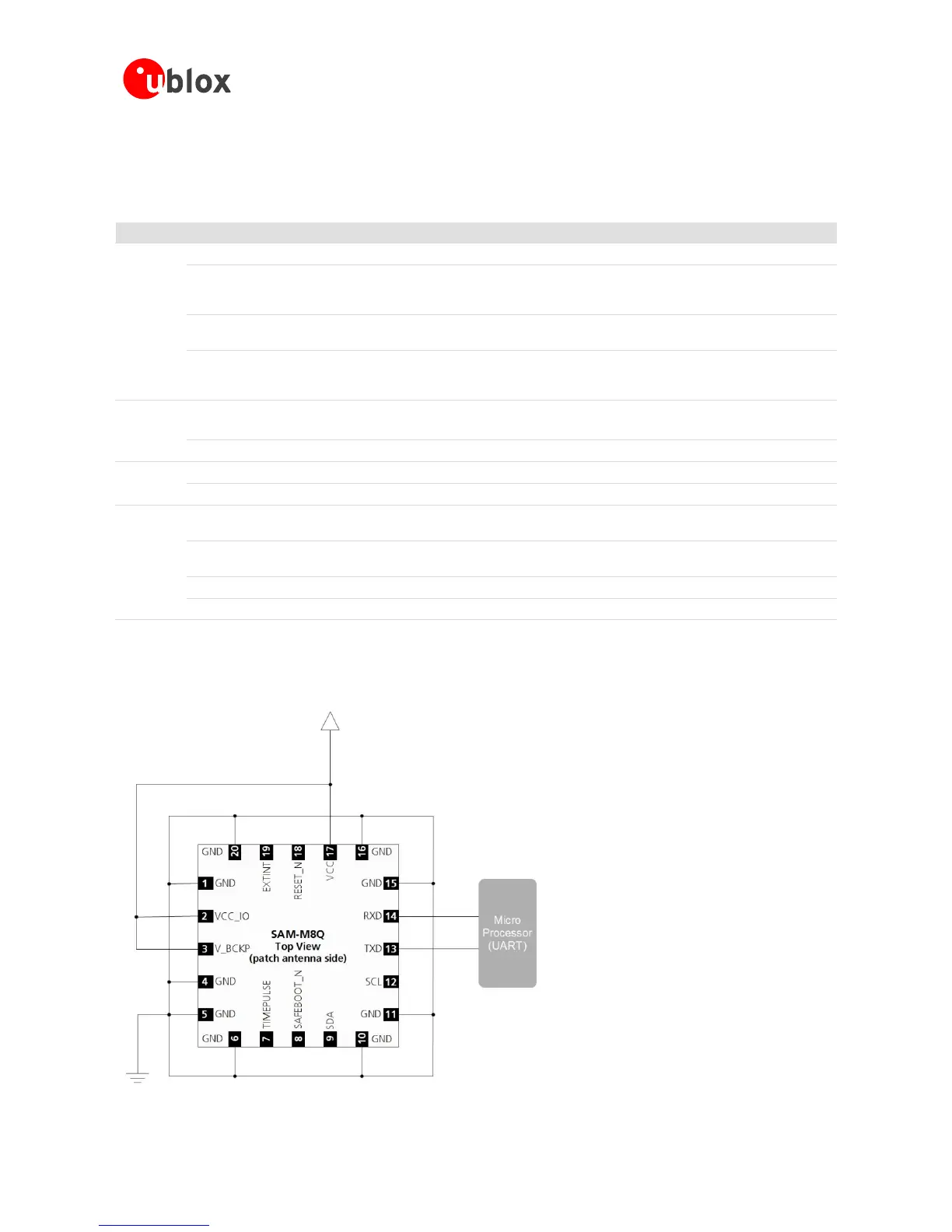
2.2 Minimal design
This is a minimal setup for a SAM-M8Q GNSS antenna module:
Figure 3: SAM-M8Q GNSS patch antenna design

 Loading...


