EVK-R5 - User guide
UBX-19042592 - R06 Starting up Page 7 of 23
C1-Public
1.4 LEDs
Power supply plugged in the 9 - 18 V Power Input
Cellular module supplied. Main power switch must be switched on.
Cellular USB
(single UART)
USB cable plugged in the Cellular USB connector (J501) for access to
the cellular single UART interface (with default USIO variant 0, or USIO
variant 1)
Cellular USB
(single UART)
Green light is activated when the SW401 is in “on-board” position, and
the cellular single UART interface (with default USIO variant 0, or USIO
variant 1) is routed to the Cellular USB connector (J501).
Red light blinks at TX or RX data on the Cellular USB connector.
Cellular single UART
attach/detach
Green light is activated when the signals of the cellular single UART
interface (with default USIO variant 0, or variant 1) are available on the
USB / RS232 connectors (J500 / J501) on the EVB-WL3
Cellular RS232
(single UART)
Green light is activated when the cellular single UART interface (with
default USIO variant 0, or USIO variant 1) is routed to the
Cellular RS232 connector (J500).
Red light blinks at TX or RX data on the Cellular RS232 connector.
RI line turns ON (active low)
CTS line turns ON (active low)
Green light is activated when cellular GPIO1 is high
Green light is activated when cellular GPIO2 is high
Green light is activated when cellular GPIO3 is high
Green light is activated when cellular GPIO4 is high
USB cable plugged in the Cellular native USB connector on the
ADP-R5, for access to the cellular USB interface
USB cable plugged in the Cellular USB connector (J201) on the
ADP-R5, for access to the two UART interfaces (USIO variant 2, 3 or 4)
Cellular two UARTs
attach/detach
Green light is activated when the SW401 is on the “B2B” position at
module’s boot, and the two UART interfaces (with USIO variant 2, 3 or
4) are routed to the Cellular USB connector (J201) on the ADP-R5
GNSS module supply is turned on
USB cable plugged into the GNSS USB connector
Pulses at 1 Hz when valid GNSS fix
Cellular / GNSS module communication over the I2C interface
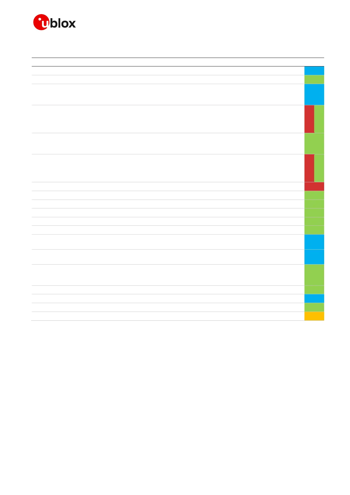
Table 2: EVK-R5 LED descriptions

 Loading...


