Service Manual UPO1000X Series
Instruments.uni-trend.com
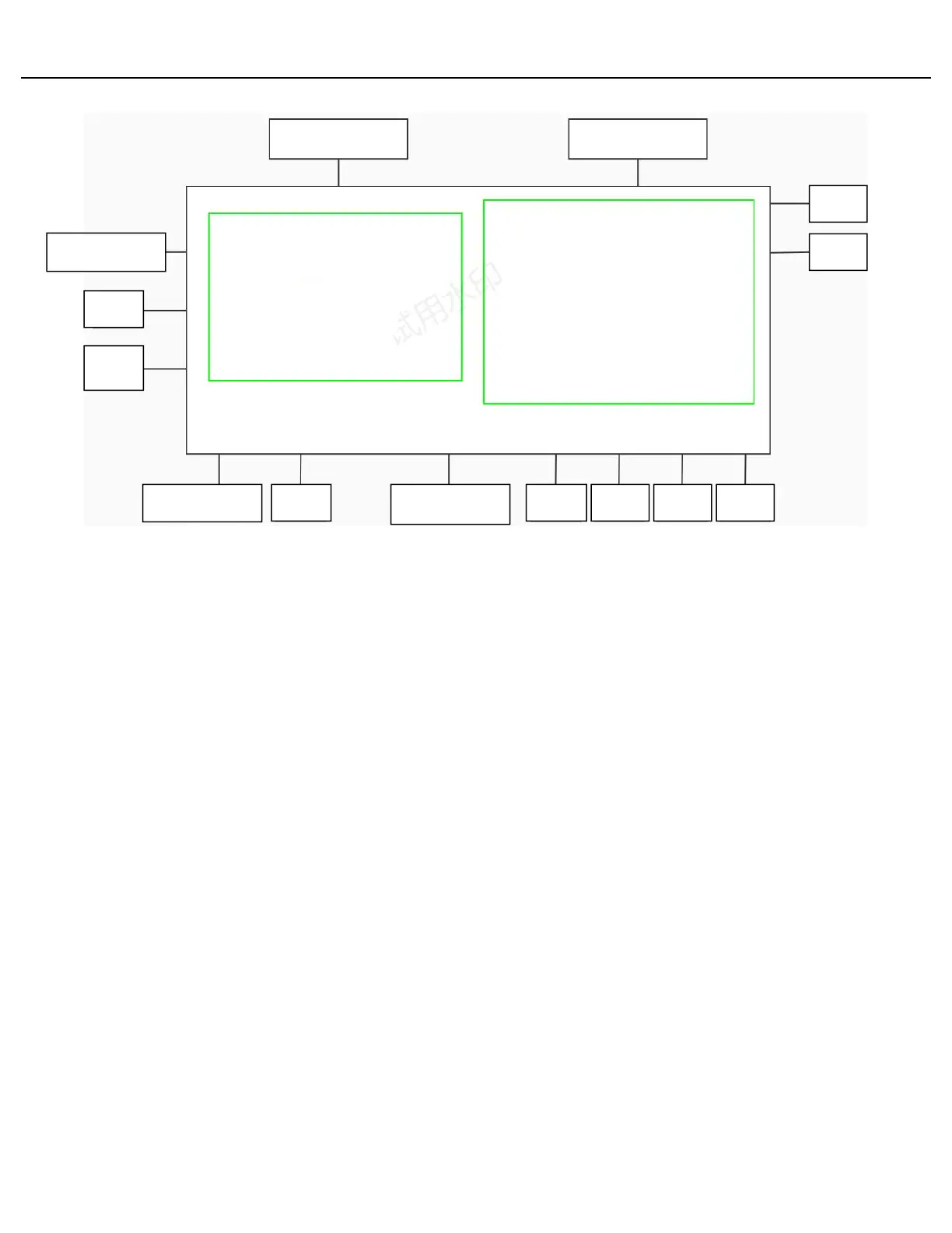
Figure 1 UPO1000X Series Block Diagram
Power Supply
The Power Supply board converts AC line voltage to secondary electric power supply for all internal circuits.
Main Board
The Main boards contain the following functions.
The Acquisition system begins with the analog signal path and ends with a
digitized signal in memory. The signal enters a channel input, and then passes
through an attenuator and preamplifier. The analog signal from each
preamplifier goes through a digitizer, and then into acquisition memory. The
analog signal from each preamplifier is also distributed to a trigger circuit.
All analog and digital input are routing to the analog front end. Analog channel
can be magnified or attenuated via front-end circuit and output to the
acquisition ASIC. Digital channel only needs to pass through the front-end
circuit to reach the acquisition ASIC.
Processing the data the analog front end and the data from keyboard and send
the data collected by analog front panel to the screen according to the input
command by the keyboard.
Power supply converts to all voltages used for analog and digital circuits
throughout the system. The standby power supply is used to keep power for
certain parts of the system at all times when AC power is connected to the
instrument.
 Loading...