Use the diode test to check diodes, transistors, and other
semiconductor devices. The diode test sends a current
through the semiconductor junction, and then measures
the voltage drop across the junction. A good silicon junction
drops between 0.5V and 0.8V
To test out a diode out of a circuit, connect the Meter as
follows:
1. Insert the red test lead into the Hz VΩ (UT58C) or
VΩ (UT58A/UT58B) terminal and the black test
lead into the COM terminal
2. Set the rotary switch to .
3. For forward voltage drop readings on any semiconductor
component, place the red test lead on the component’s
anode and place the black test lead on the component’s
cathode.
The measured value shows on the display.
l The open-circuit voltage is around 3V.
l When diode testing has been completed, disconnect
the connection between the testing leads and the
circuit under test.
Measurement Operation(7)
black red
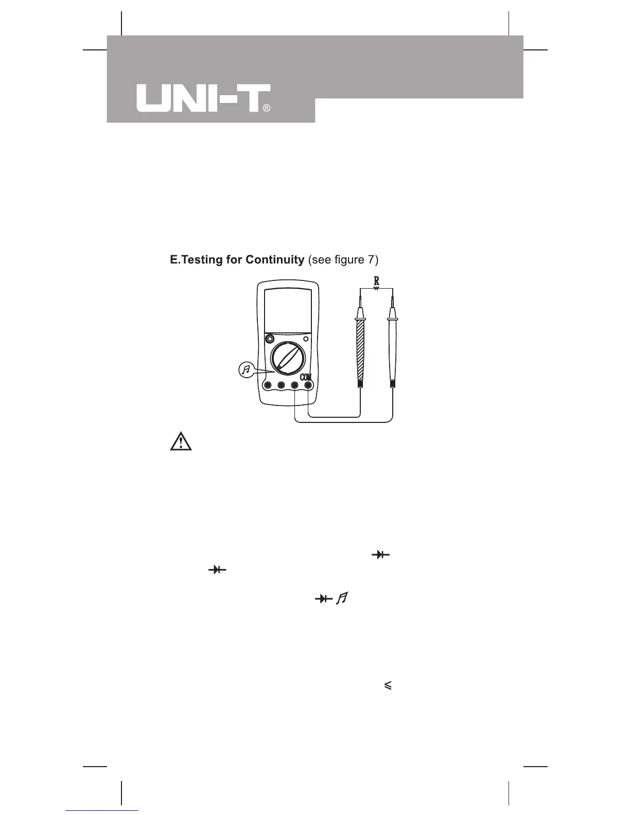
(figure 7)
Warning
To avoid harms to you, please do not attempt to input
voltages higher than 60V DC or 30V rms AC.
To avoid damages to the Meter or to the devices under
test, disconnect circuit power and discharge all the
high-voltage capacitors before testing for continuity.
To test for continuity, connect the Meter as below:
1. Insert the red test lead into Hz VΩ (UT58C)
or
VΩ (UT58A/UT58B) terminal and the black test
lead into the COM terminal.
2. Set the rotary switch to
.
3. Connect the test leads across with the object being
measured.
4. The buzzer does not sound if the resistance of a
circuit under test is >70
Ω
The buzzer sounds continuously if the circuit is in
good condition with resistance value 10
Ω
.
The measured value shows on the display and the
unit is
Ω
.
Model UT58A/B/C: OPERATING MANUAL
20

 Loading...