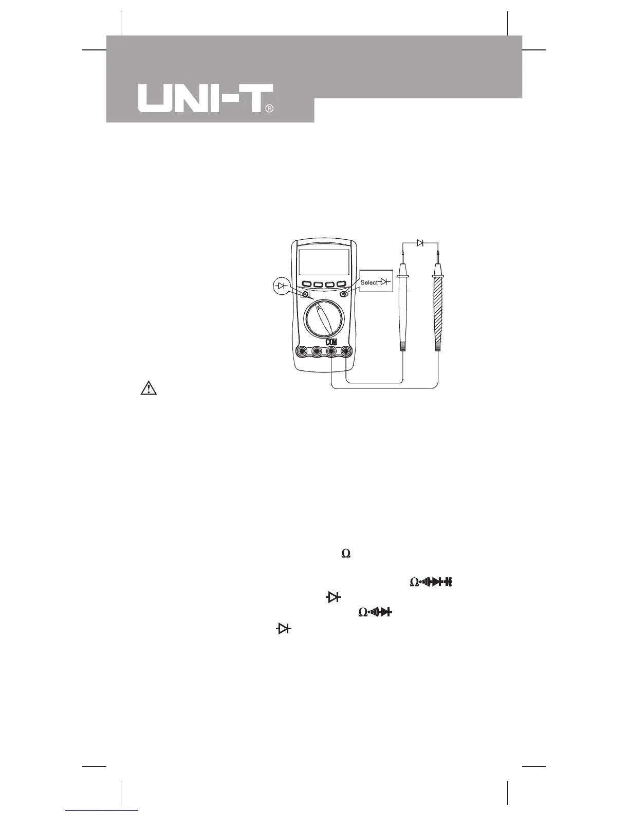
E. Testing Diodes
(see figure 7)
To avoid possible damage to the Meter and to the device
under test, disconnect circuit power and discharge all high-
voltage capacitors before testing diodes.
Use the diode test to check diodes, transistors, and other
semiconductor devices. The diode test sends a current through
the semiconductor junction, and then measures the voltage drop
across the junction. A good silicon junction drops between
0.5V and 0.8V.
Warning
l When continuity testing has been completed, disconnect the
connection between the testing leads and the circuit under
test, and remove the testing leads away from the input
terminals of the Meter.
3. For forward voltage drop readings on any semiconductor
component, place the red test lead on the component’s anode
and place the black test lead on the component’s cathode.
The measured value shows on the display.
Note
l In a circuit, a good diode should still produce a forward
To test a diode out of a circuit, connect the Meter as follows:
Insert the red test lead into the
HzV
terminal and the black
testlead into the COM terminal.
2. Model UT60C/UT60E: Set the rotary switch to
measurement mode.
Model UT60B:Set the rotary switch to and press
measurement mode.
and press BLUE button to select
BLUE button to select
Measurement Operation (5)
(figure 7)
1.
18
Model UT60B/C/E: OPERATING MANUAL
 Loading...