EasyManua.ls Logo

UNI-T UTD2102CEX+ User Manual

UNI-T UTD2102CEX+
65 pages
To Next Page IconTo Next Page
To Previous Page IconTo Previous Page
Page #33 background image
UTD2000 Series User Manual
33
4.6 Trigger Holdoff
Trigger holdoff time adjustment is used to observe complex waveform (pulse string series).
Holdoff time refers to the waiting time for the DSO to restart trigger circuit. During holdoff
time, the DSO will not trigger until the holdoff time is over.
Table 4-9 Trigger Holdoff Menu
Function Menu
Setting
Description
Window extension
On/off
Press to turn on the main time base.
Time base selection
Main time
base/extensive
time base
Main time base: set as main time base, the main time base will
change when adjusting horizontal time base.
Extension time base: set as extension time base, the extension time
base will change when adjusting horizontal time base.
Window extension
——
Press to turn on the extension time base.
Hold off time
To adjust the trigger hold-off time by multi-purpose knob.
Take pulse series as example, trigger the first pulse on the pulse series, then the holdoff
time can be set as pulse string width. As shown in the figure below:
Figure 4-4 Snychronous complex waveform
Operation Instruction:
(1) Based on the synchronization mode of normal signal, select to trigger edge, trigger
source, slope of TRIG MENU and adjust trigger level to make the waveform stable as
possible.
(2) Press HORI MENU to display horizontal menu.
(3) By adjusting the multifunctional knob, the holdoff time will be changing until the
waveform is stable.
4.7 Explanation of nouns
(1) Trigger source: Trigger can be achieved from several signal sources: input channels
(CH1 and CH2), external triggers (EXT) and AC line.
Input channel: The most frequently-used trigger source is input channel (selectable).
The selected channel as trigger source can operate normally no matter its input is
displayed or not.

Table of Contents

Question and Answer IconNeed help?

Do you have a question about the UNI-T UTD2102CEX+ and is the answer not in the manual?

UNI-T UTD2102CEX+ Specifications

General IconGeneral
BrandUNI-T
ModelUTD2102CEX+
CategoryTest Equipment
LanguageEnglish

Summary

General Safety Overview

Safety Terms and Symbols

Defines safety terms like Danger, Warning, Note and lists product symbols with descriptions.

Chapter I: Introduction and System Basics

Initial Inspection and Functionality Check

Steps for inspecting the instrument and its accessories after purchase for damage or completeness.

Front and Rear Panel Layout

Identification and explanation of controls and connectors on the front and rear panels of the oscilloscope.

Display Screen Elements

Description of the waveform display window, main time base, and horizontal trigger area.

Vertical System Overview

Introduction to the vertical control area, including position and scale adjustments.

Horizontal System Overview

Introduction to the horizontal control area, including position and scale adjustments.

Trigger System Overview

Overview of the trigger control area, including level adjustment and trigger menu options.

Chapter II: Vertical System Configuration

Channel Coupling and Bandwidth Settings

Setting channel coupling (AC, DC, GND) and bandwidth limit (Full BW, 20MHz).

Probe Attenuation and Volts/Div Adjustment

Setting probe attenuation coefficient and adjusting vertical scale (Volts/Div).

Waveform Inverting Function

Enables or disables waveform inversion for channels, flipping the display 180 degrees.

Mathematical Operations and FFT Analysis

Performing mathematical operations (+, -, x, ÷) on channels and FFT spectral analysis.

Digital Filtering Capabilities

Applying digital filters (low pass, high pass, band pass, band stop) to signals.

Chapter III: Horizontal System Controls

Horizontal Control Knob and Menu Functions

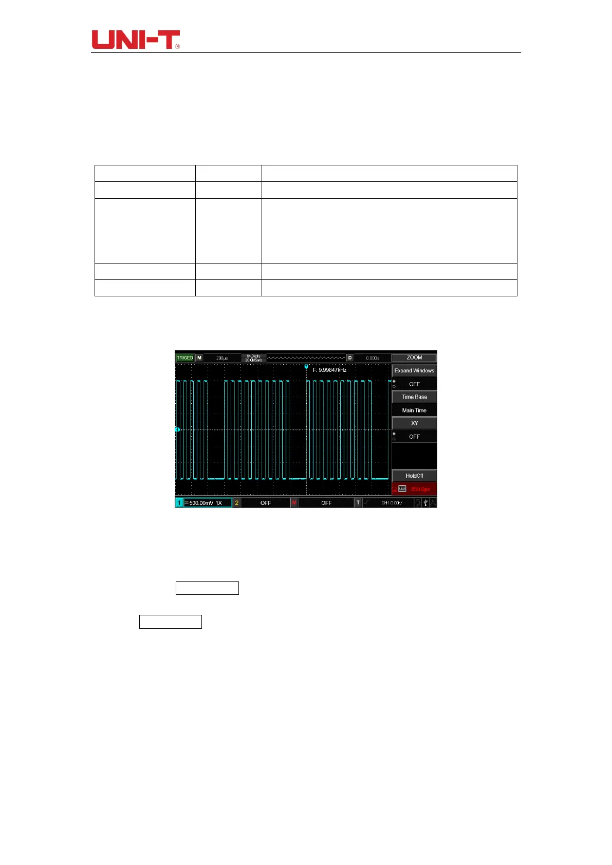
Adjusting horizontal time base scale, position, and accessing zoom/holdoff menus.

Window Extension and XY Mode Operation

Using window extension for detailed waveform viewing and XY mode for phase analysis.

Chapter IV: Trigger System Configuration

Edge and Pulse Width Triggering

Configuring edge trigger (rising/falling) and pulse width trigger conditions.

Slope, Video, and Alternating Triggers

Setting up slope, video (NTSC/PAL), and alternating triggers for signal capture.

Trigger Holdoff and Source Selection

Adjusting trigger holdoff time and selecting trigger sources (CH1, CH2, EXT, AC Line).

Chapter V: Acquire System Functions

Acquisition Modes and Settings Explained

Detailed explanation of acquisition modes like Sampling, Peak Value, Average, and Fast Acq.

Chapter VI: Display System Settings

Display Types and Screen Adjustment

Configuring display types (Vector, Dots), persistence, and screen brightness.

Chapter VII: Automatic Measurement Features

Measurement Menu and Parameters

Accessing the measurement menu and selecting up to 34 waveform parameters.

Voltage and Time Parameter Definitions

Detailed definitions and diagrams for voltage (Vpp, Vmax, Vmin) and time (Rise, Fall, Period) parameters.

Chapter VIII: Cursor Measurement

Cursor Measurement Setup and Usage

Setting up cursors for time and voltage measurements and understanding the display.

Chapter IX: Storage and Data Management

Setting, Storing, and Loading Data

Configuring storage type, medium, saving, and loading settings and waveforms.

Waveform and Bitmap Storage Options

Storing waveforms as data files (CSV) and screen copies as bitmaps (BMP).

Chapter X: Utility System Functions

Pass/Fail Test and Recorder Functions

Performing pass/fail tests against templates and recording waveforms frame-by-frame.

AUTO Strategy and System Configuration

Configuring AUTO strategy parameters and system setup options like self-calibration.

Chapter XI: Other Function Buttons

AUTO Setting and RUN/STOP Operation

Using the AUTO button for waveform setup and RUN/STOP for measurement control.

Help Menu and Software Upgrade Guide

Accessing the help menu and performing software upgrades via USB.

Chapter XII: Application Examples

Measuring Simple Signals and Delays

Examples for measuring signal frequency, peak-to-peak value, and observing signal delay.

Single Signal Acquisition and Noise Reduction

Techniques for acquiring single signals and reducing random noise using sampling modes.

Cursor Measurement Applications

Using cursors to measure voltage differences in step signals.

Chapter XIII: System Prompts and Troubleshooting

System Prompt Definitions

Explanation of various system prompts that may appear during operation.

Troubleshooting Common Oscilloscope Issues

Guidance on resolving issues like no waveform display, voltage test problems, and trigger failures.

Chapter XIV: Technical Specifications

Chapter XV: Appendix

Accessories, Maintenance, and Warranty

Lists standard/optional accessories, provides maintenance guidelines, and details warranty information.

Contact and Support Information

Provides contact details for product support and UNI-T sales centers.

Related product manuals