EasyManua.ls Logo

UNI-T UTD2152CL User Manual

UNI-T UTD2152CL
65 pages
To Next Page IconTo Next Page
To Previous Page IconTo Previous Page
Page #33 background image
UTD2000 Series User Manual
33
4.6 Trigger Holdoff
Trigger holdoff time adjustment is used to observe complex waveform (pulse string series).
Holdoff time refers to the waiting time for the DSO to restart trigger circuit. During holdoff
time, the DSO will not trigger until the holdoff time is over.
Table 4-9 Trigger Holdoff Menu
Function Menu
Setting
Description
Window extension
On/off
Press to turn on the main time base.
Time base selection
Main time
base/extensive
time base
Main time base: set as main time base, the main time base will
change when adjusting horizontal time base.
Extension time base: set as extension time base, the extension time
base will change when adjusting horizontal time base.
Window extension
——
Press to turn on the extension time base.
Hold off time
To adjust the trigger hold-off time by multi-purpose knob.
Take pulse series as example, trigger the first pulse on the pulse series, then the holdoff
time can be set as pulse string width. As shown in the figure below:
Figure 4-4 Snychronous complex waveform
Operation Instruction:
(1) Based on the synchronization mode of normal signal, select to trigger edge, trigger
source, slope of TRIG MENU and adjust trigger level to make the waveform stable as
possible.
(2) Press HORI MENU to display horizontal menu.
(3) By adjusting the multifunctional knob, the holdoff time will be changing until the
waveform is stable.
4.7 Explanation of nouns
(1) Trigger source: Trigger can be achieved from several signal sources: input channels
(CH1 and CH2), external triggers (EXT) and AC line.
Input channel: The most frequently-used trigger source is input channel (selectable).
The selected channel as trigger source can operate normally no matter its input is
displayed or not.

Table of Contents

Question and Answer IconNeed help?

Do you have a question about the UNI-T UTD2152CL and is the answer not in the manual?

UNI-T UTD2152CL Specifications

General IconGeneral
BrandUNI-T
ModelUTD2152CL
CategoryTest Equipment
LanguageEnglish

Summary

General Safety Overview

Safety Precautions and Guidelines

Essential safety measures for operating the oscilloscope to prevent injury and damage.

Mains Supply Cord Set Specification

Details the specifications for power cords suitable for different regions (EU, US/CAN).

Safety Terms and Symbols

Safety Terms and Definitions

Explains safety terms like Danger, Warning, and Note used in the manual and on the product.

Chapter I Introductions

Chapter II Vertical System

Setting Channel Coupling Modes

How to configure AC, DC, or GND coupling for input channels.

Channel Bandwidth Limit Configuration

Setting the bandwidth limit for signal acquisition to filter frequencies.

Probe Attenuation Setting

Adjusting the probe attenuation coefficient for accurate vertical scale readings.

Vertical Volts/Div Adjustment

Setting the vertical scale (Volts/Div) for signal amplitude display.

Chapter III Horizontal System

Horizontal Control Knobs and Buttons

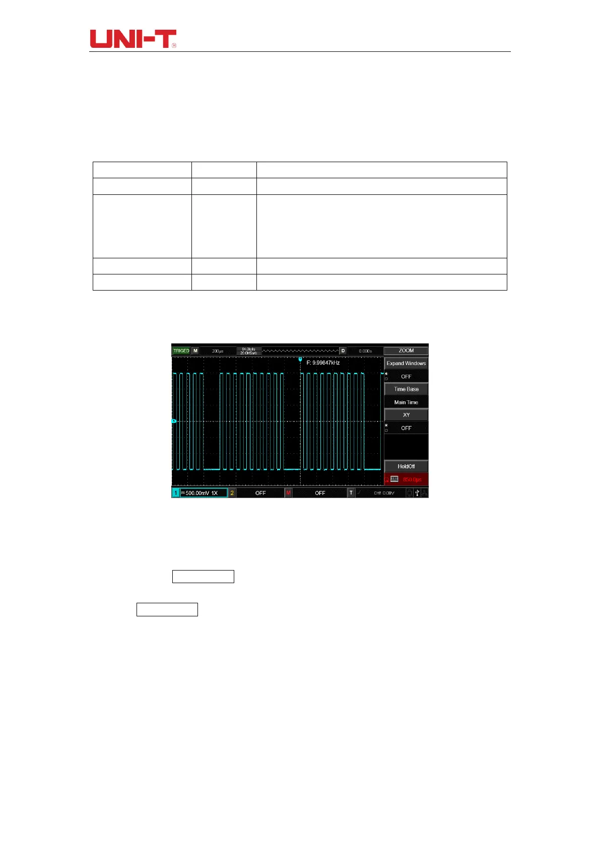
Operating horizontal time base scale and position controls.

Chapter IV Trigger System

Edge Trigger Configuration

Setting triggers based on signal edge transitions (rising/falling).

Pulse Width Trigger Settings

Triggering based on the duration of a pulse (positive or negative).

Slope Trigger Configuration

Triggering based on the rate of signal rise or fall.

Chapter V Acquire System

Acquire Function Menu and Modes

Settings for data acquisition modes: Sampling, Peak Value, Average, etc.

Chapter VI Display System

Chapter VII Automatic Measurement

Automatic Measurement Menu

Accessing and configuring the automatic measurement functions.

Voltage Measurement Parameters

Details of voltage parameters like Vmax, Vmin, Vpp measured by the DSO.

Time Measurement Parameters

Details of time parameters like Period, Rise Time, Fall Time measured by the DSO.

Other Measurement Parameters

Other waveform parameters including duty cycle, overshoot, and phase.

Chapter VIII Cursor Measurement

Cursor Measurement Menu Setup

Configuring cursor type (voltage/time), mode, unit, and source.

Cursor Measurement Display and Usage

How to use cursors to measure voltage and time differences on waveforms.

Chapter X Utility System

AUTO Strategy Configuration

Customizing the behavior of the AUTO waveform setting function.

Chapter XI Other Function Buttons

AUTO Setting Operation

Using the AUTO button for automatic adjustment of waveform display.

RUN/STOP Button Functionality

Controlling the oscilloscope's acquisition state between running and stopping.

Chapter XIII System Prompts and Troubleshooting

Troubleshooting Common Issues

Solutions for common problems like no waveform display or trigger instability.

Related product manuals