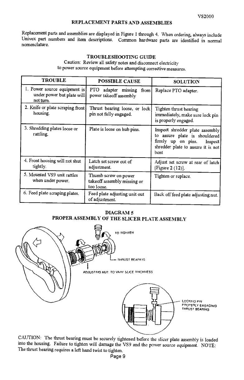
DIAGRAM 5
PROPER ASSEMBLY OF THE SLICER PLATE ASSEMBLY
THflUST EEATIUIG
ADJUSTING NUT: 10 VA1Y SUCE 1I4ICTIESS
VS2000
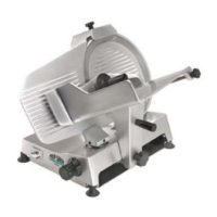
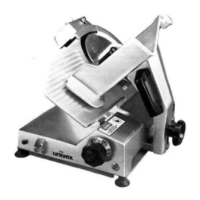
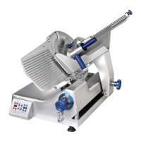
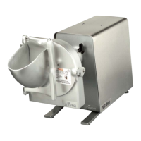
REPLACEMENT PARTS AND ASSEMBLIES
Replacement parts and assemblies are displayed in Figure 1 through 4. When ordering, always
include
Univex part numbers and item descriptions.
Common hardware parts are identified in normal
nomenclature.
TROUBLESHOOTING GUIDE
Caution: Review all safety notes and disconnect electricity
to power source equipment before attempting corrective measures.
IOCI<ITIG PIN
PPOT'ETT(Y ENGAGING
n-must
BEAnI NG
CAUTION: The thrust bearing must be securely tightened before the slicer plate
assembly is loaded
into the housing. Failure to tighten will damage the VS9 and the
power source equipment. NOTE:
The thrust bearing requires a left hand twist to tighten.
Page 9
TROUBLE
-
POSSIBLE CAUSE
SOLUTION
1. Power source equipment is
under power but plate will
notturn.
PTO adapter
missing from
power takeoff assembly
Replace PTO adapter.
2. Knife or plate scraping front
housing.
Thrust bearing loose, or lock
pin not fully engaged.
Tighten thrust bearing
immediately, make sure lock pin
is properly engaged.
3. Shredding plates loose or
rattling,
Plate is loose on hub pins.
Inspect shredder plate assembly
to
assure
plate
is
shouldered
firmly up on pins.
Inspect
shredder plate to assure it is not
bent
4. Front housing will not shut
tightly.
Latch set screw out of
adjustment.
Adjust set screw at rear of latch
[Figure 2 (12)].
5. Mounted VS9 unit rattles
when under power.
Thumb screw on power
takeoff assembly missing or
too loose.
Tighten or replace.
6. Feed plate scraping plates.
Feed plate adjusting unit out
of adjustment.
Back off feed plate adjusting nut.
PDF compression, OCR, web optimization using a watermarked evaluation copy of CVISION PDFCompressor
 Loading...