ENGLISH
- 10 -
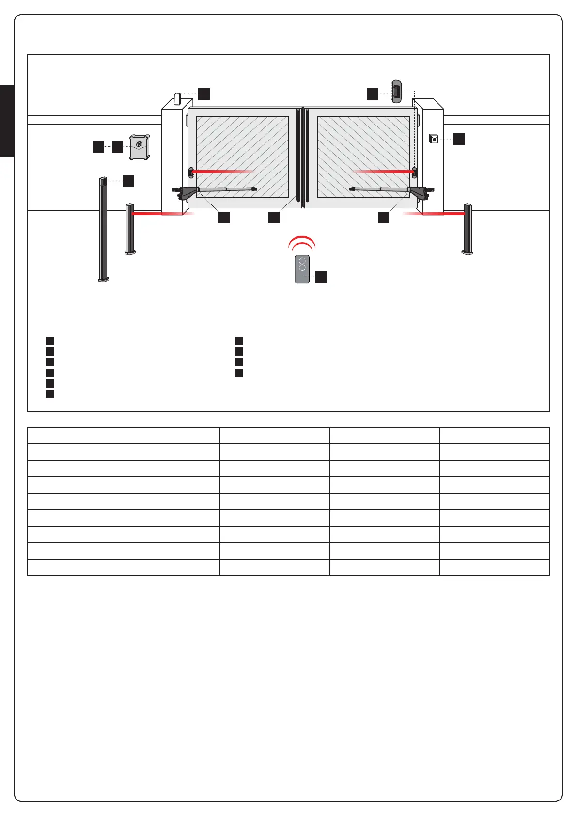
INSTALLATION LAYOUT
A
B
C
D
1
2
3
4
5
6
Key switch
Pillar photocells
Pillar-mounted digital radio switch
Safety edges
Motor
Control unit
Transmitter
Receiving module
Photocells
Flashing light
COMPONENTS ADDITIONAL ACCESSORIES
LENGTH OF THE CABLE < 10 metres from 10 to 20 metres from 20 to 30 metres
Power supply (230/120V) 3G x 1,5 mm
2
3G x 1,5 mm
2
3G x 2,5 mm
2
230/120V motor power supply 4G x 1,5 mm
2
4G x 1,5 mm
2
4G x 2,5 mm
2
Photocells (TX) 2 x 0,5 mm
2
2 x 0,5 mm
2
2 x 0,5 mm
2
Photocells (RX) 4 x 0,5 mm
2
4 x 0,5 mm
2
4 x 0,5 mm
2
Key switch 2 x 0,5 mm
2
2 x 0,5 mm
2
2 x 0,5 mm
2
Safety edges 2 x 0,5 mm
2
2 x 0,5 mm
2
2 x 0,5 mm
2
Flashing light 2 x 1,5 mm
2
2 x 1,5 mm
2
2 x 1,5 mm
2
Antenna (integrated into the flashing light) RG174 RG174 RG174
1 1D
3
A
C
2
56
4
 Loading...