POLSKI
- 46 -
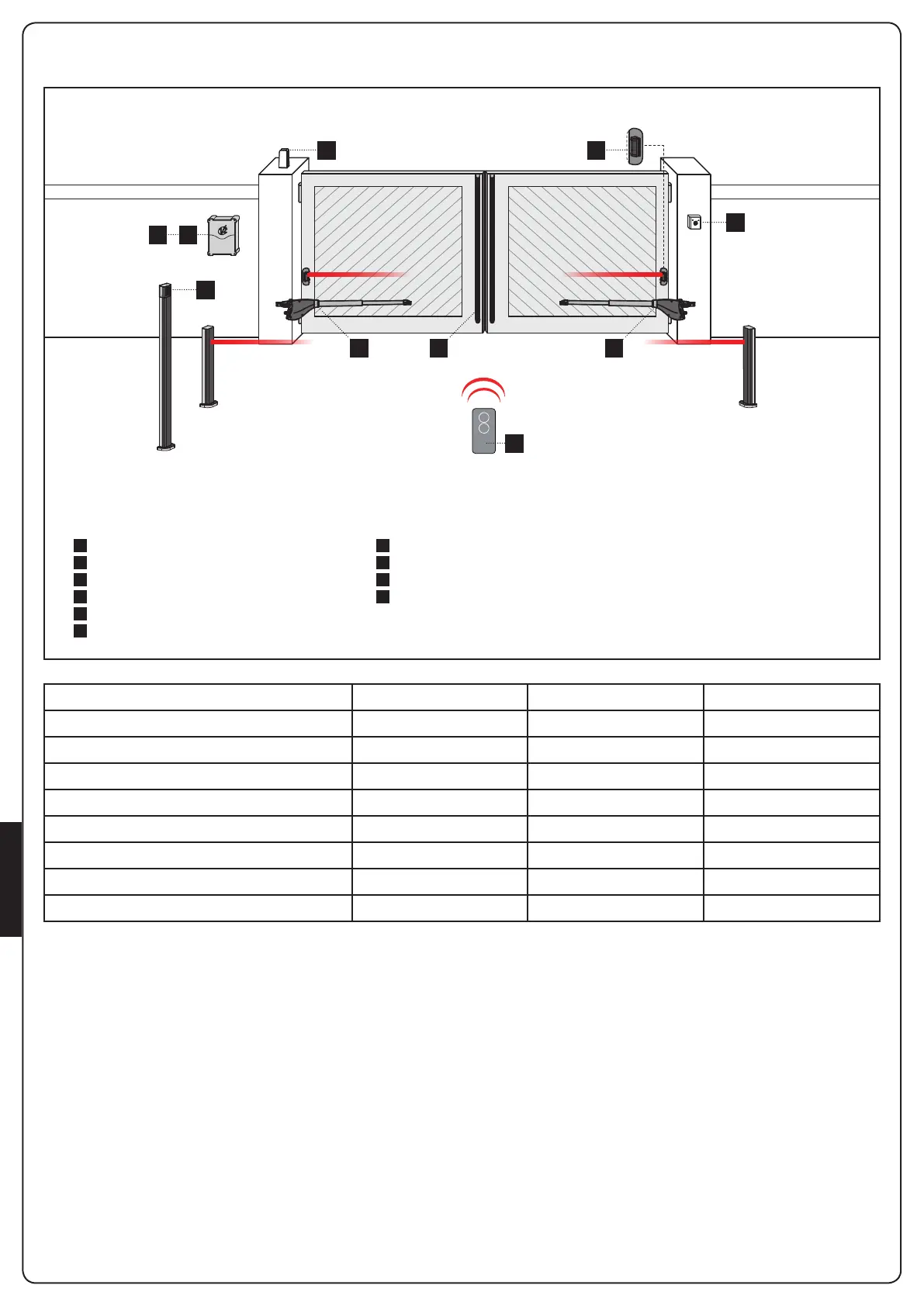
SCHEMAT INSTALACJI
A
B
C
D
1
2
3
4
5
6
Przełącznik kluczowy
Fotobariery
Przełącznik cyfrowy
Listwa bezpieczeństwa
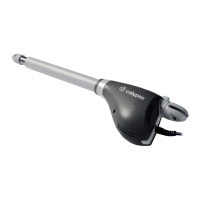
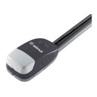
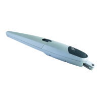
Siłownik
Centralka sterownicza
Nadajnik
Moduł odbiorczy
Fotobariery
Lampa ostrzegawcza
SKŁADNIKI DODATKOWE AKCESORIA
DŁUGOŚĆ KABLA < 10 metr 10 - 20 metr 20 - 30 metr
Zasilanie 230/120V 3G x 1,5 mm
2
3G x 1,5 mm
2
3G x 2,5 mm
2
Zasilanie silnika (230/120V) 4G x 1,5 mm
2
4G x 1,5 mm
2
4G x 2,5 mm
2
Fotobariery (TX) 2 x 0,5 mm
2
2 x 0,5 mm
2
2 x 0,5 mm
2
Fotobariery (RX) 4 x 0,5 mm
2
4 x 0,5 mm
2
4 x 0,5 mm
2
Przełącznik kluczowy 2 x 0,5 mm
2
2 x 0,5 mm
2
2 x 0,5 mm
2
Listwa bezpieczeństwa 2 x 0,5 mm
2
2 x 0,5 mm
2
2 x 0,5 mm
2
Lampa ostrzegawcza 2 x 1,5 mm
2
2 x 1,5 mm
2
2 x 1,5 mm
2
Antena RG174 RG174 RG174
1 1D
3
A
C
2
56
4