ENGLISH
14
INSTALLING THE MAGNETIC LIMIT SWITCHES
Install the supplied magnet holder on the rack in a way that, in the opening and closing limit positions, the magnet be
positioned next to the magnetic sensor behind the hood (as near as possible to the hood).
The supplied magnets have been colored differently in order to be distinguished from each other:
RED MAGNET = CLOSING LIMIT SWITCH
BLUE MAGNET = OPENING LIMIT SWITCH
The limit switches are wired for installation with the motor on
the right of the gate opening.
If the motor is installed on the left of the gate opening, it will be
necessary to invert the blue and brown cables on the limit switch
and also the motor connector (C1-C2-C3) on the control unit.
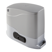
INSTALLING THE MECHANICAL
LIMIT SWITCHES
Install limit switches on the rack and fix them using the screws
provided in the tool kit.
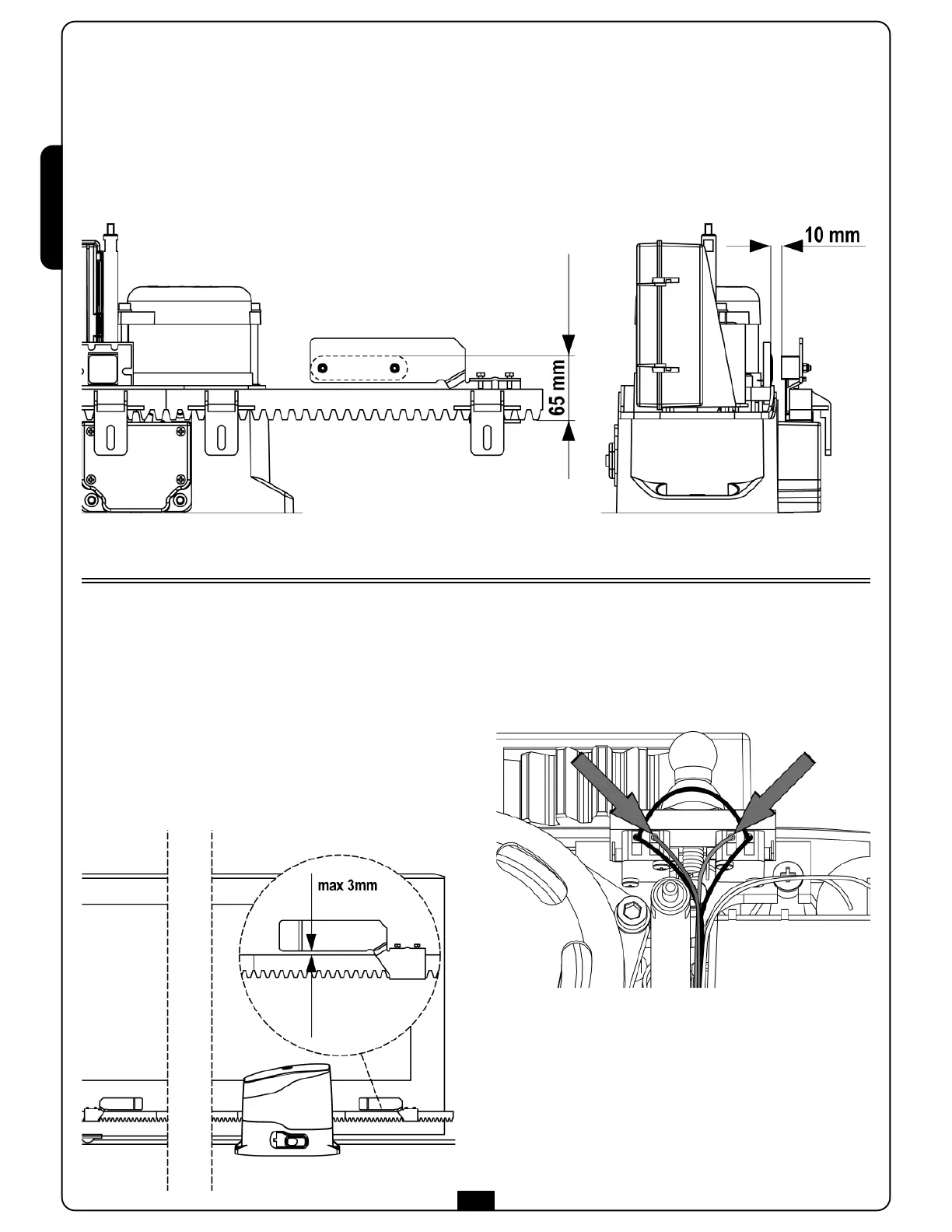
ATTENTION: check that the limit switch bracket will
work effectively on the limit switch spring of the motor.
If necessary add thickness between the lower part of the
rack and the limit switch bracket in order to keep to the
measurement as stated in the figure.
 Loading...