10
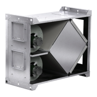
Energy Core Ventilator
ERV Specifications
AC Input Power
1115Vac, 230Vac, 277Vac 50/60 Hz.
Motor and Aux Input
115Vac — 208Vac Input, 50/60 Hz.
230Vac — 277Vac Input, 60/60 Hz.
Motor Output
QTY (2) 115Vac 8.8FLA 3/4HP
QTY (1) Wheel Motor 115Vac 0.75 FLA
Remote ON Input
Provide a close contact between TB2-1 and TB2-2 will
active the ERV Controller.
Sensor Remote Power
+24Vdc Pin 3 of TB2 and GND Pin 4 of TB2 is available
for source powering sensors. (Maximum 100ma).
Frost Control
Extremely cold outdoor air temperatures can cause
moisture condensation and frosting on the energy
recovery wheel. Frost Control timer is a selectable
timer control that will prevent control wheel frosting.
Frost control uses a Therm-O-Disc P/N: 314886 T-O-D
60T11 (L15-10F) mounted in the outdoor air intake
compartment. Thermo-O-Disc has pre-set temperature
of 5°F and uses the normally closed contacts; contacts
open on temperature rise. Use the test procedure for
troubleshooting.
Remote Thermostat/Therm-O Disc Input:
Wire between Pins 5 and 6 of TB2.
Single Mode Speed Control
Place SW2 slide switch on ERV PCB to the
Single
position.
Provide a 0- 10Vdc command signal to Pin 7 (-)
and Pin 8 (+) of TB2. This will control the speed of both
A and B motors.
Dual Mode Speed Control
Place SW2 slide switch on ERV PCB to the dual mode.
Provide a 0-10Vdc command signal to Pin 7 (-) and Pin
8 (+), of TB2 for speed control of Motor A. Provide
another 0-10V command signal to Pin 9 (-) and Pin 10
(+) of TB2 for speed control of Motor B.
Inlet/Outlet Motor Swap
In the event the Inlet and Exhaust vents are swapped,
slide SW1 switch on ERV PCB A and B motors to
reverse.
Agency Approval: UL E479135
Conditions of Acceptability
1. ERV Controller must be mounted in a suitable
end-use enclosure.
2. Load motors rated 3/4HP shall be R/C (XDNW2)
Electronically Protected Motor with Locked Rotor
Protection.
Timer Settings:
T1 ON Timer T2 OFF Timer
0 = 5 MIIN 0 = 5 MlN (default)
1 = 10 MIN 1 = 10 MIN
2 = 15 MIN 2 = 15 MIN
3 = 20 MIN 3 = 20 MIN
4 = 25 MIN 4 = 25 MIN
5 = 30 MIN (default) 5 = 30 MIN
6 = 35 MIN 6 = 35 MIN
7 = 40 MIN 7 = 40 MIN
Operation
IMPORTANT: Ensure all wiring is complete before
applying power to the ERV controller.
Check Voltage
Before starting the ERV Controller, compare the
supplied voltage with the unit’s nameplate voltage and
the motor voltage.
Initial Setup
1. Apply power to the ERV controller.
2. Remote ON: To turn ‘’ON” the ERV Controller,
provide a close contact between Pins 1 and 2 of
TB2 on ERV PCB. The Green LED will illuminate
when activated {“ON”)
3. Validate Motor operation: With Remote “ON”
activated, verify Energy Wheel, Inlet and Exhaust
motors are functioning.
Note: If A or B motor is “OFF”, check the
following:
a. Frost control maybe activated depending on
the Thermostat input Pins 5 and 6 of TB2.
b. 0-10Vdc Speed Controls settings are too
low. From 0-1.9V, the A and B motor(s) will
be off and will operate within the 2-10V
range.
4. Validate lnlet and Outlet (Exhaust) motor operation
with setting of SW1 on the ERV Controller. Make
sure SW1 is in the correct position A or B. If the
Inlet and Outlet (Exhaust) are reserved, simply
slide SW1 switch on the ERV PCB to the opposite
position. This will swap Inlet and Outlet motors
without re-wiring.
5. If +24Vdc is required for Remote sensor power, ,
validate +24Vdc between Pins 3 and Pin 4 (GND)
of TB2. (Maximum 100ma).
 Loading...