7
Energy Core Ventilator
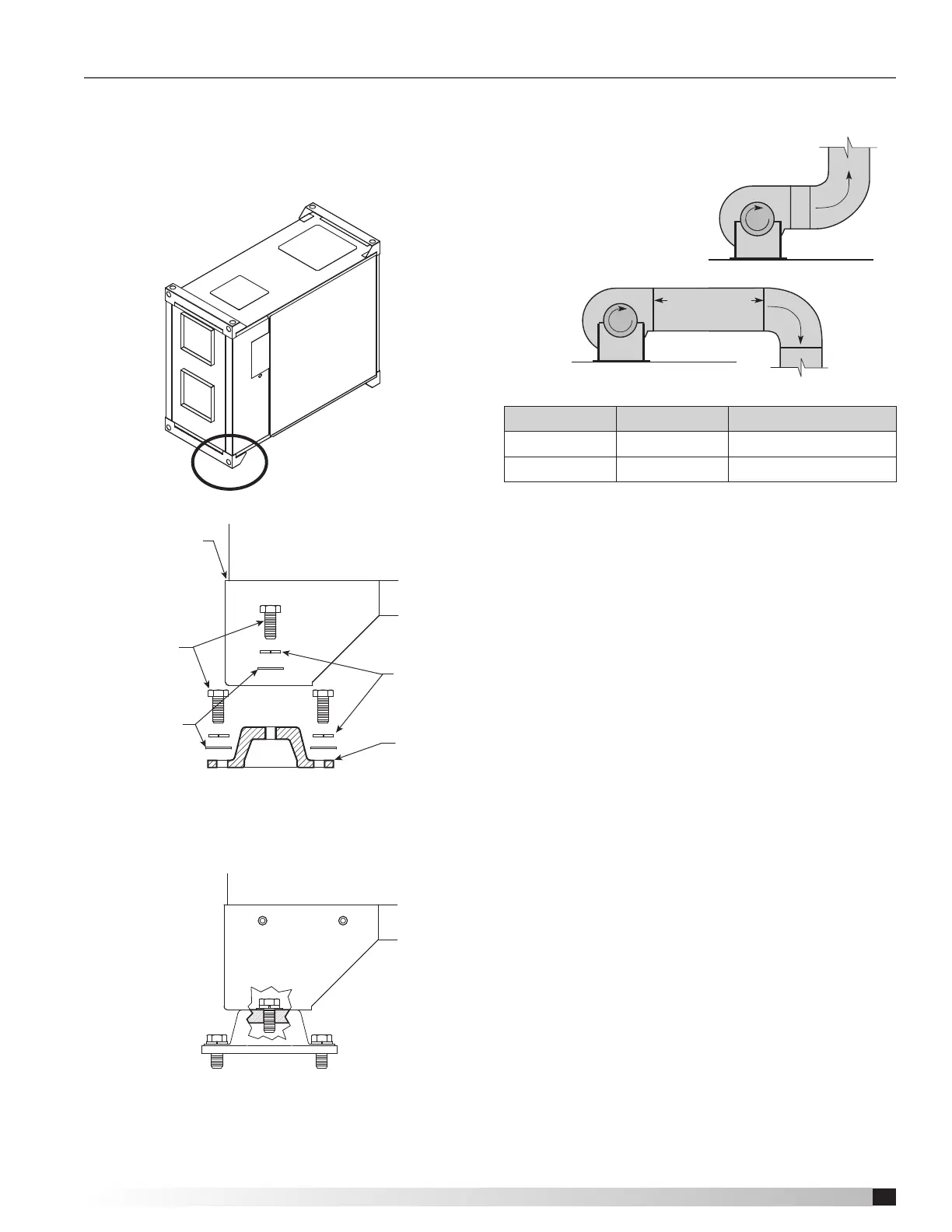
Base Vibration Isolator Assembly
3/8-inch bolt
Factory-mounted
bracket
Lock washer
Flat washer
Isolator
Assembled and Mounted Isolator Detail
Recommended Discharge Duct Size and Length
Model Duct Size Straight Duct Length
ERC-M1
9.75 3
ERC-M2
9.75 3
• Recommended duct sizes are based on velocities across the
airflow range of each model at approximately 800 feet per minute
(PM) at minimum airflow and up to 1600 fpm at maximum airflow.
Recommended duct sizes are only intended to be a guide and
may not satisfy the requirements of the project. Refer to plans for
appropriate job specific duct size and/or velocity limitations.
• Straight duct lengths were calculated based on 100% effective
duct length requirements as prescribed in AMCA Publication
201. Calculated values have been rounded up to nearest foot.
1 Fan
Wheel
Dia.
1 Fan
Wheel
Dia.
R
o
t
a
t
i
o
n
R
o
t
a
t
i
o
n
R
o
t
a
t
i
o
n
R
o
t
a
t
i
o
n
Length of Straight Duct
GOOD
POOR
GOODPOOR
GOOD
POOR
Tu rning
Vanes
Tu rning
Vanes
SYSTEM EFFECT FACTOR CURVES
FPM X 100
OUTLET VELOCITY
0 5 10 15 20 25 30 35 40 45
1.2
1.0
0.8
0.6
0.4
0.2
0.0
STATIC PRESSURE LOSS
CURVE 1
CURVE 2
CURVE 3
CURVE 4
Ductwork Connections
Examples of poor and good fan-to-duct connections
are shown. Airflow out of the fan should
be directed straight or curve the
same direction as the
fan wheel rotates. Poor
duct installation will result
in low airflow and other
system effects.
1 Fan
Wheel
Dia.
1 Fan
Wheel
Dia.
R
o
t
a
t
i
o
n
R
o
t
a
t
i
o
n
R
o
t
a
t
i
o
n
R
o
t
a
t
i
o
n
Length of Straight Duct
GOOD
POOR
GOODPOOR
GOOD
POOR
Tu rning
Vanes
Tu rning
Vanes
SYSTEM EFFECT FACTOR CURVES
FPM X 100
OUTLET VELOCITY
0 5 10 15 20 25 30 35 40 45
1.2
1.0
0.8
0.6
0.4
0.2
0.0
STATIC PRESSURE LOSS
CURVE 1
CURVE 2
CURVE 3
CURVE 4
Base Mounting
with Base Vibration Isolators
• The base isolators kit includes four (4) isolators,
four (4) brackets and required hardware.
• Assemble and mount the isolators as shown in the
figures below.
Installation
 Loading...