c
e
r
t
i
f
i
e
d
Q
M
-
S
y
s
t
e
m
g
e
p
r
ü
f
t
e
s
Q
M
-
S
y
s
t
e
m
ISO 9001
EN 29001
Installation, Operating, and Maintenance Instructions
Series 64.1
VAT Vakuumventile AG, CH-9469 Haag, Schweiz
Tel ++41 81 771 61 61 Fax ++41 81 771 48 30 Email reception@vat.ch http://www.vatvalve.com
225590EE
2005-04-26
4/16
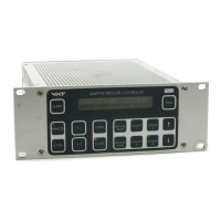
2.3 PM Configuration (setup sequence)
STEP
LOCAL MODE (PM-4 in combination with
Service Box only)
REMOTE MODE (PM-5 if interface installed
only)
1
POWER ON
1. PM controller: Turn on power switch at the rear panel of the PM controller. Note: Valve will close, if not in
closed position
2. On PM-5 or Service Box start-up display (Software version, type of interface, etc.) appears, until valve is in
closed position
3. CLOSE(D) is displayed, otherwise please refer to chapter ‘6 Trouble Shooting’.
2
SELECT
MODE
Select LOCAL operation by pressing «LOCAL» key for 2
seconds.
Select REMOTE operation by pressing «REMOTE» key
on front panel or Service Box for 2 seconds or select
remote operation through RS232 (see ‚9.3.1 Control
commands’) or logic interface (see ‚9.1.3.1 Logic
interface‘)
3
AUTOMATIC
SIZE
ADJUSTMENT
Press simultaneously «OPEN» and «CLOSE» keys for 2
seconds. The controller will perform an automatic size
adjustment procedure to determine open and closed
position and the range between the two positions.
Send RS232 command:
J:<CR><LF> (see ‚9.3.1 Control commands’)
or use Logic command (see ‚9.1.3.1 Logic interface‘)
4
SENSOR
SETUP
1)
Press simultaneously «LEARN» and «ZERO» key for 2
seconds (notation used hereafter: «&», e.g. «LEARN» &
«ZERO»). Then, use «↑» and «↓» key to change
parameters (VOLTAGE RANGE; DISPLAY RANGE;
DISPLAY UNIT; GAIN FACTOR; SENSOR TYPE; ZERO
ADJUST) for each sensor. Toggle with «F1» key to the
next setup parameter. Press «F2» , when finished.
See ‚9.3.3 Sensor setup command‘
Example:
Sensor 1, Voltage Range: 0-10V; Display Range: 0-10;
Display Unit: Torr; Gain Factor: 1; Sensor Type: Torr;
Zero Adjust: enabled;
s:1332010<CR><LF>
Mind: Not possible to do by a logic interface.
5
ZERO ADJUST
(Offset
compensation of
sensor output)
Evacuate process chamber to high vacuum. When the
base pressure is reached, press «ZERO» key for 2
seconds to reset the offset of the pressure sensor.
Disable ZERO function in SENSOR SETUP, if the base
pressure of your system is higher than 1‰ of sensor full
scale.
Evacuate process chamber to high vacuum. When the
base pressure is reached send RS232 command:
Z:<CR><LF> (see ‚9.3.1 Control commands’)
or use Logic command (see ‚9.1.3.1 Logic interface‘).
Disable ZERO function in SENSOR SETUP, if the base
pressure of your system is higher than 1‰ of sensor full
scale.
6
LEARN
2)
(Determination of
control
characteristics of
your process
chamber)
Process chamber at high vacuum, control valve is open:
Open gas inlet and set gas flow (see recommendation
below). Press «LEARN» key for 3 seconds to perform
the autolearning routine of the PM controller. The
autolearning routine may take several minutes and can
be aborted by pressing the «F1» key. A single full run of
the autolearning routine is required to ensure fast and
accurate pressure control.
Note: It is not necessary to repeat LEARN, if the
sensor setup is changed, or if the second
sensor is selected for pressure control. The
controller covers 5% to 5000% of the gasflow
which was used at LEARN.
Process chamber at high vacuum, control valve is open:
Open gas inlet and set gas flow (see recommendation
below). Then send RS232 LEARN command:
L:001000<CR><LF> (‚9.3.1 Control commands’)
or Logic command (see ‚9.1.3.1 Logic interface‘).
The autolearning routine may take several minutes. A
single full run of the autolearning routine is required to
ensure fast and accurate pressure control.
Note: It is not necessary to repeat LEARN, if the
sensor setup is changed, or if the second
sensor is selected for pressure control. The
controller covers 5% to 5000% of the gasflow
which was used at LEARN.
Legend:
1)
The default GAIN FACTOR is 1.00. See chapter ‚9.3.3 Sensor setup command‘ if resetting is necessary.
gain factor > 1 means: faster control but higher overshoot of pressure
gain factor < 1 means: slower control but lower overshoot of pressure
Just 98% of sensor pressure range can be used during control.
If no sensor is used, select as display parameter ‘POS’.
2)
Ideal gasflow for autolearning
Q = 40
•
p
SFS
•
L
min
Q...........gasflow for autolearning [sccm]
p
SFS
.......sensor full scale pressure [Torr]
L
min
........min. controllable conductance [l/s]
Do not use a different gasflow than
recommended for autolearning otherwise
pressure control performance may be insufficient.
valve size DN63 DN100 DN160 DN200 DN250 DN320 DN400
min. controllable conductance 0.6 l/s 1 l/s 1.6 l/s 2 l/s 2.5 l/s 3.2 l/s 4 l/s
 Loading...