V-123
1. Diagram
www.vax.co.uk
2
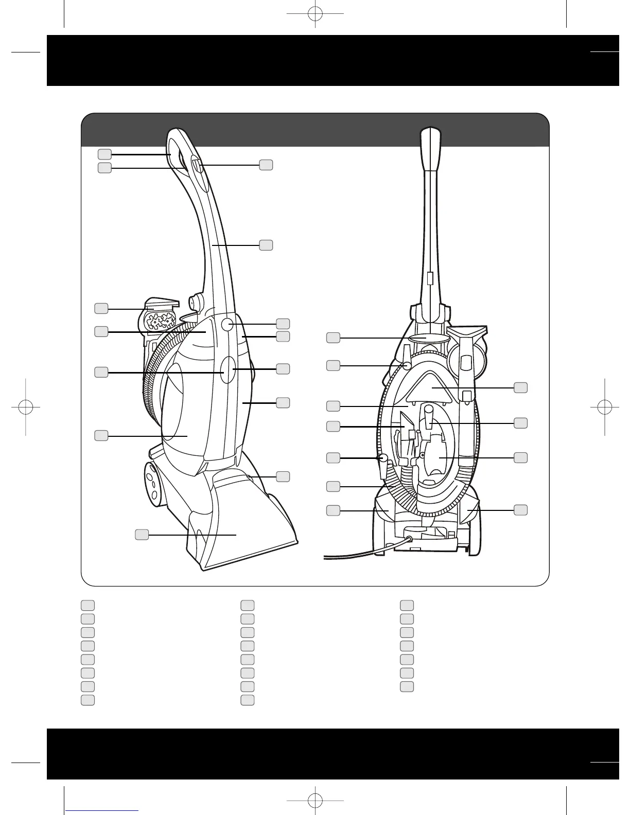
parts overview
1
2
6
3
4
7
8
9
5
15
16
21
16
23
22
21
20
19
14
13
12
10
11
Fig.1/1
1 Handle grip
2 Solution trigger
3
Clean Surge button
4 Upper handle
5 Upper handle release button
6 Solution tank cap/measuring cup
7 Solution tank release button
8 Solution tank
9 Brush setting selector
10 Nozzle
11
Recovery tank
12 Recovery tank release button
13 Recovery tank cap
14
P
owered SpinScrub hand tool
15 Stair/upholstery tool
16
Cable hooks
(t
ool caddy removed)
17 Hose inlet
18 Handle release pedal
19
On/Off pedal
20 Hose
21 Cable hooks
(tool caddy in place)
22
Hose c
onnector
23 Tool caddy
17
18
Vax V-123 User Guide.qxd 10/8/07 15:43 Page 2

 Loading...