Do you have a question about the Vega VEGABAR 55 and is the answer not in the manual?
Provides information for mounting, connection, setup, maintenance, and fault rectification.
Manual is for trained qualified personnel. Contents must be made available.
Explains symbols like Information, Caution, Warning, Danger, Ex applications, List, Action, Sequence.
Covers authorised personnel, appropriate use, misuse warnings, general safety, labels, CE conformity.
Covers Ex areas, environmental instructions, NAMUR recommendations.
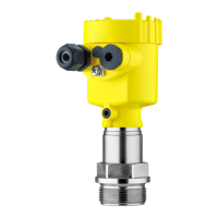
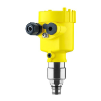
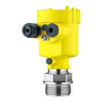
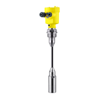
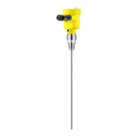
Details scope of delivery and components of the VEGABAR 55 pressure transmitter.
Explains application area, measuring cell, and output signal conversion.
Covers operation, packaging, transport, storage, and accessories.
Covers suitability, mounting position, and moisture protection.
Details on sealing, screwing into sockets, and flange connections.
Instructions for wall mounting including drilling template and screw torque.
Safety instructions, overvoltage arresters, hazardous area considerations, power supply.
Step-by-step guide for connecting the device, including housing cover, cable entry, terminals.
Wiring plans for single chamber, IP 66/68, and external housing versions.
Describes the self-check procedure after connecting power.
Module use for display, adjustment, diagnosis. Steps to insert/remove.
Explains the indicating and adjustment elements and key functions.
Outlines setup for level or process pressure, unit selection, and adjustments.
Visual menu structure and data saving recommendations.
Routine maintenance, cleaning, and steps to remove interferences and causes.
Formulas and example for calculating total deviation according to DIN 16086.
Procedures for exchanging electronics module and updating software.
Procedure for instrument repair, including download of return form.
Warning about process conditions before dismounting. Steps in reverse order.
Information on recycling, WEEE directive, and professional disposal.
General data, communication, materials, weights, and output variables.
Max output, load, NAMUR, dynamics, input, adjustment ranges.
Measuring ranges, overload, reference conditions, deviation.
Reference conditions, deviation calculations, thermal change, stability.
Electromechanical data for IP 66/IP 67 versions.
Electromechanical data for IP 68 versions.
Indicating/adjustment module data, power supply voltages.
Voltage diagram, electrical protective measures, functional safety (SIL).
Information on approvals and where to find related documents.
Housing versions with dimensions and identification.
Housing versions in protection IP 66/IP 68 (1 bar) with dimensions.
External housing with IP 68 version, showing dimensions and cable outlets.
VEGABAR 55 threaded fitting dimensions for various types.
VEGABAR 55 hygienic fitting 1 dimensions for various types.
VEGABAR 55 hygienic fitting 2 dimensions for various types.
VEGABAR 55 flange connection dimensions.
Information on VEGA's industrial property rights and website.
Statement about brands and company names belonging to their proprietors.
Provides information for mounting, connection, setup, maintenance, and fault rectification.
Manual is for trained qualified personnel. Contents must be made available.
Explains symbols like Information, Caution, Warning, Danger, Ex applications, List, Action, Sequence.
Covers authorised personnel, appropriate use, misuse warnings, general safety, labels, CE conformity.
Covers Ex areas, environmental instructions, NAMUR recommendations.
Details scope of delivery and components of the VEGABAR 55 pressure transmitter.
Explains application area, measuring cell, and output signal conversion.
Covers operation, packaging, transport, storage, and accessories.
Covers suitability, mounting position, and moisture protection.
Details on sealing, screwing into sockets, and flange connections.
Instructions for wall mounting including drilling template and screw torque.
Safety instructions, overvoltage arresters, hazardous area considerations, power supply.
Step-by-step guide for connecting the device, including housing cover, cable entry, terminals.
Wiring plans for single chamber, IP 66/68, and external housing versions.
Describes the self-check procedure after connecting power.
Module use for display, adjustment, diagnosis. Steps to insert/remove.
Explains the indicating and adjustment elements and key functions.
Outlines setup for level or process pressure, unit selection, and adjustments.
Visual menu structure and data saving recommendations.
Routine maintenance, cleaning, and steps to remove interferences and causes.
Formulas and example for calculating total deviation according to DIN 16086.
Procedures for exchanging electronics module and updating software.
Procedure for instrument repair, including download of return form.
Warning about process conditions before dismounting. Steps in reverse order.
Information on recycling, WEEE directive, and professional disposal.
General data, communication, materials, weights, and output variables.
Max output, load, NAMUR, dynamics, input, adjustment ranges.
Measuring ranges, overload, reference conditions, deviation.
Reference conditions, deviation calculations, thermal change, stability.
Electromechanical data for IP 66/IP 67 versions.
Electromechanical data for IP 68 versions.
Indicating/adjustment module data, power supply voltages.
Voltage diagram, electrical protective measures, functional safety (SIL).
Information on approvals and where to find related documents.
Housing versions with dimensions and identification.
Housing versions in protection IP 66/IP 68 (1 bar) with dimensions.
External housing with IP 68 version, showing dimensions and cable outlets.
VEGABAR 55 threaded fitting dimensions for various types.
VEGABAR 55 hygienic fitting 1 dimensions for various types.
VEGABAR 55 hygienic fitting 2 dimensions for various types.
VEGABAR 55 flange connection dimensions.
Information on VEGA's industrial property rights and website.
Statement about brands and company names belonging to their proprietors.
| Brand | Vega |
|---|---|
| Model | VEGABAR 55 |
| Category | Transmitter |
| Language | English |