Vertiv | NetSure Rectifier Module User Manual (UM1R483500e) | Rev. R
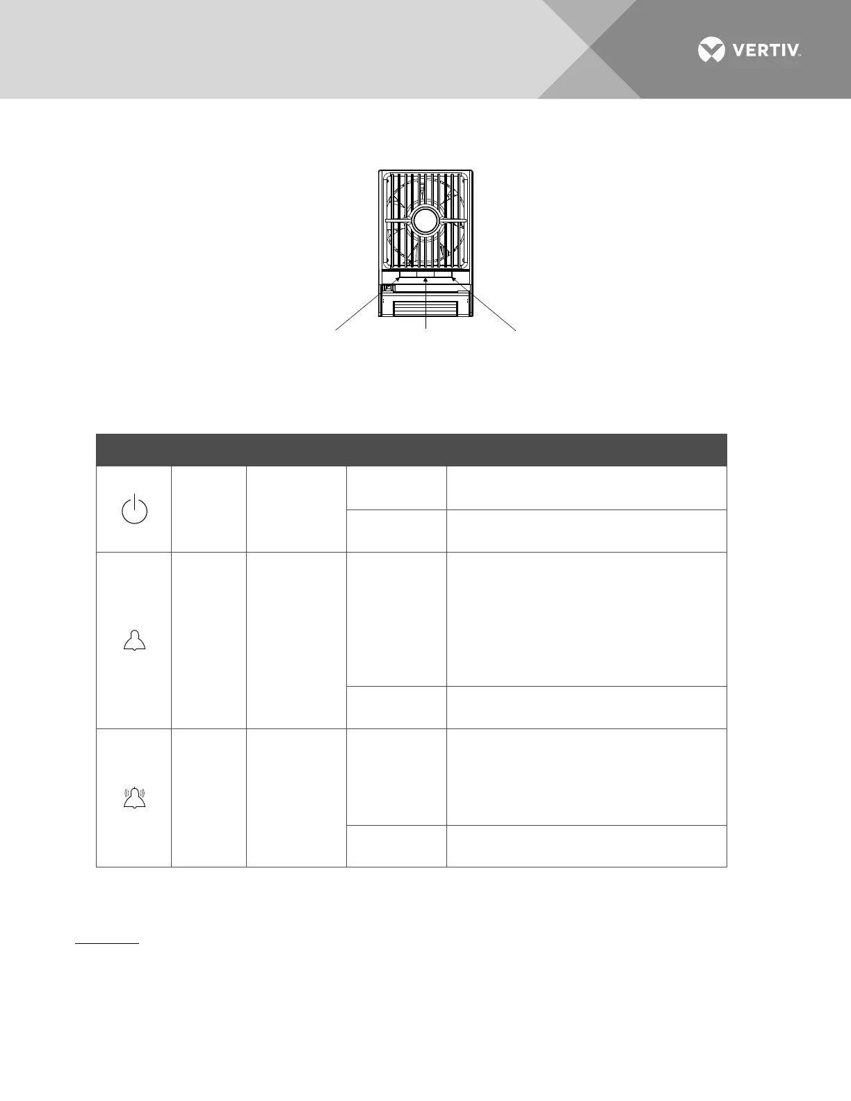
Figure 15:
Local Indicator Locations
Table 2:
Local Indicators
Indicator Normal State Alarm State Alarm Cause
Power
(Green)
On
Off
No input voltage.
Internal input fuse open.
Flashing
The rectifier is being identified by the
controller.
Protection
(Yellow)
Off
On
AC input under/over voltage.
PFC output under/over voltage.
Moderate load sharing imbalance.
Rectifier not inserted into the slot
completely.
Rectifier in ECO Standby Mode when ECO
Mode is active in controller.
Flashing
Loss of communication with the controller
(the rectifier can provide power).
Alarm
(Red)
Off
On
Severe load sharing imbalance.
Rectifier output disabled for any reason,
including overvoltage shutdown and
internal output fuse open.
Rectifier addresses contradictory.
Flashing
Fan not operating (rectifier module shuts
down).
Rectifier High Voltage Shutdown and Lockout Restart
Procedure
1. Turn the power to the rectifier off or remove the rectifier, wait 30 seconds or more (until the LEDs on
the rectifier extinguish), then turn the power to the rectifier on or re-insert the rectifier.
Power Indicator
(Green)
Protection Indicator
(Yellow)
Alarm Indicator
(Red)

 Loading...


