Vertiv | NetSure Rectifier Module User Manual (UM1R483500e) | Rev. R
Table 1:
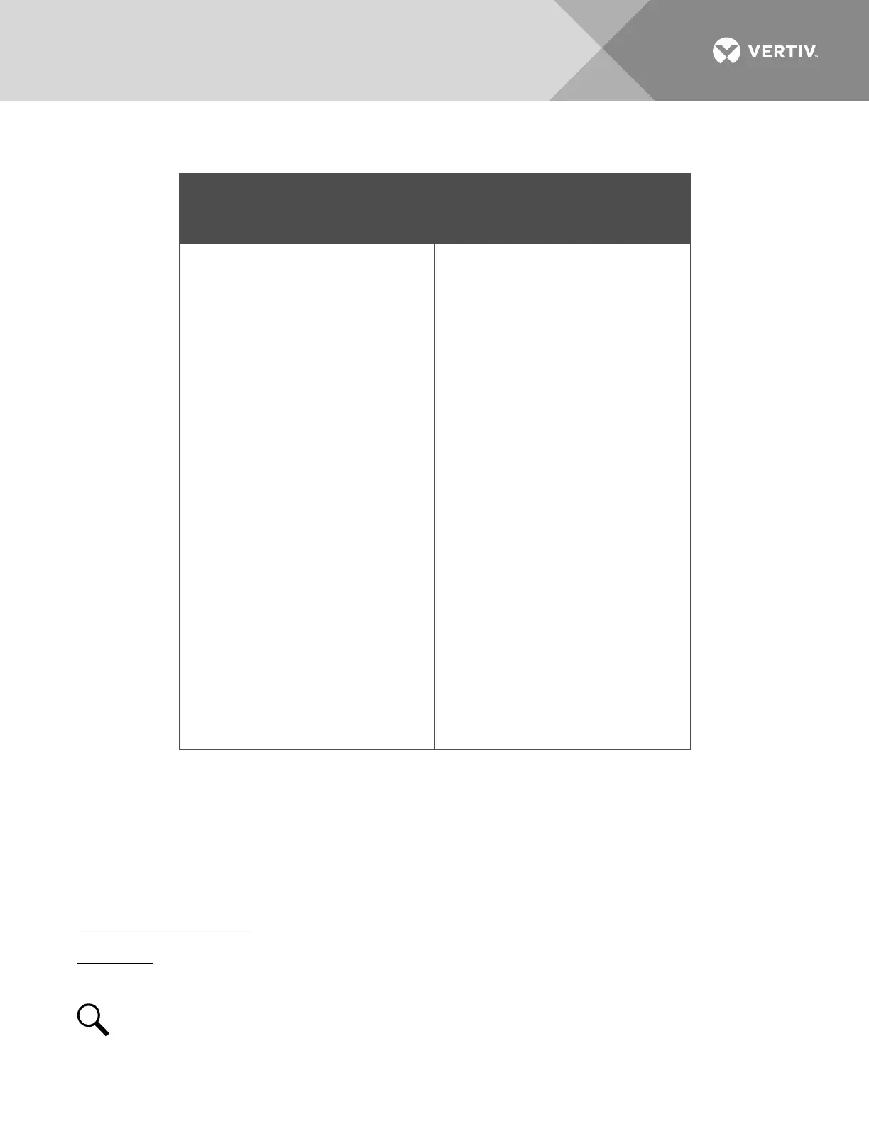
Exchange of Information between Rectifier and Controller
Commands / signals that can be
received by the Rectifier Module
from the Controller.
Information gathered by the
Controller from the Rectifier Module.
• Turn On/Off
• Current Walk-in On/Off
• HVSD (High Voltage Shutdown)
Reset
• Current Limit Adjustment
• Voltage Regulation
• Input Voltage
• Output Voltage
• Output Current
• Current Limit Setting
• Temperature
• Over Voltage Setting
• On/Off Status
• Fault Alarms, such as:
HVSD
Fan Fail
• Protection Alarms, such as:
Input Voltage Protection
Inner DC Bus Voltage Protection
High Temperature Protection
• Thermal Derating
• AC Derating
• AC Fail
• Imbalance Output Current
• Address
• Code
• Date
• Software Version
•
Hardware Version
OPERATION
AC Input Protection Device Requirements/Recommendations
Refer to the system documentation supplied with the system the rectifier is installed in.
Local Indicators
Location and Identification: Refer to Figure 15.
Description: There are three (3) indicators located on the rectifier’s front panel. The functions of these
indicators are as shown in Table 2.
NOTE!
DC voltage must be present at the rectifier output terminals (from battery or an operating
rectifier) or AC voltage at the input terminals.