33
ART.SL5418 WALL MOUNTING ART.SL5418 FISSAGGIO A PARETE
Fig.1
Fig.3 Fig.4
Fig.2
135cm
C
B
A
A
G
A
D
D
E
F
B
H
J
C
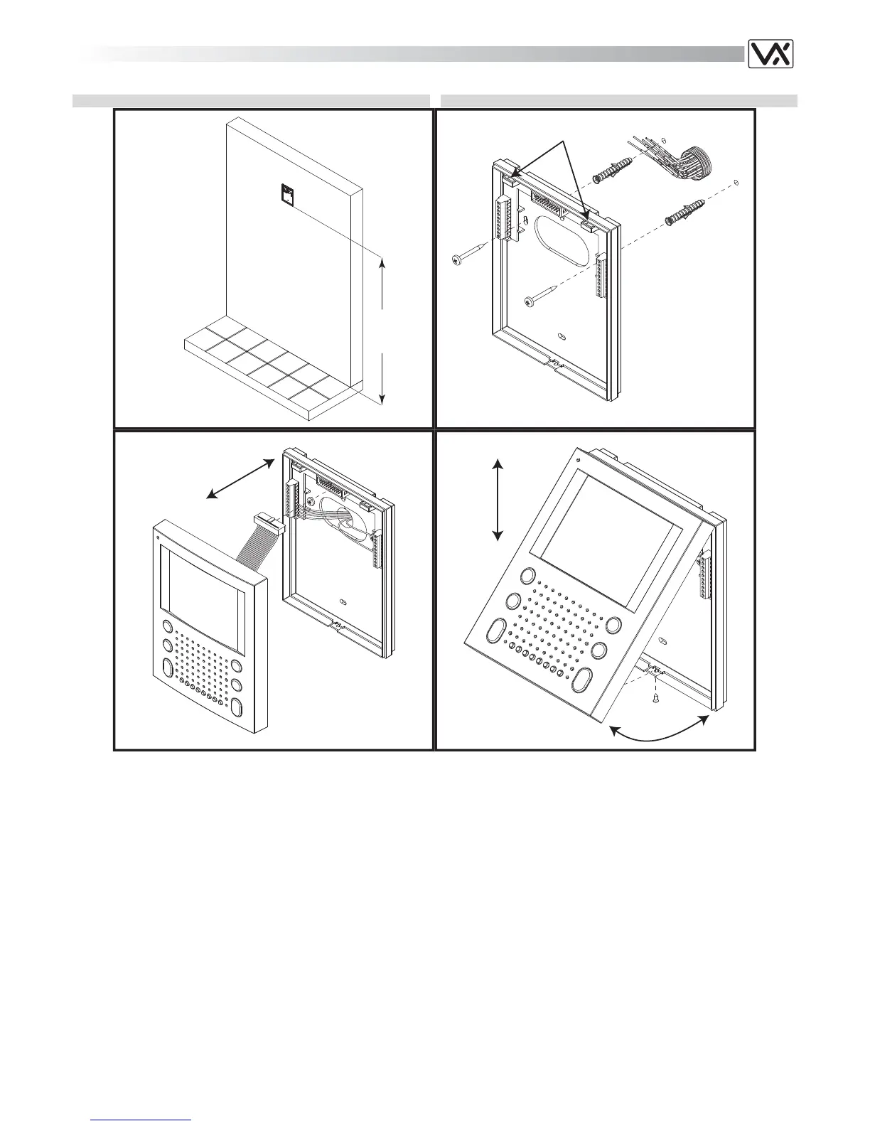
To install Art.SL5478 it is necessary to open it. Follow picture n.4:
turn screw “G”, pull cover “D” and lift it up (or push it forward if the
videomonitor is in horizontal position), then disconnect plug “E”
(Fig.3) from plug “F” on the connection board housed on the bottom
“A”.
Put the bottom “A” against the wall at 135cm from the finished floor
(Fig.1). All cables must be fed through hole “H” (Fig.2).
Leaving approximately 135cm from the finished floor, fit the bottom
“A” against the wall and mark the fixing holes considering that the
cables must fed through the opening “H” (Fig.2)
Make the holes, and fix bottom “A” on the wall using the two wall
plugs “B” and the two screws “C” as shown in figure 2.
Make all connections as per provided diagram.
As shown in figure 3, move cover “D” close to bottom “A”, connect
plug “E” to plug “F” on the connection board then proceed with the
next step.
Hook cover “D” to bottom “A” by using the two clips “J” (Fig.2) as
shown in figure 4 then push down cover “D” towards bottom “A”.
Then proceed with system testing.
When finished the testing, fix cover “D” at the bottom “A” using the
screw“G” (Fig.4).
Per installare il videocitofono Art.SL5478 è necessario aprirlo: facen-
do riferimento alla figura 4, svitare la vite “G”, tirare a se il coperchio
“D” quindi spingerlo verso l’alto (o in avanti se si effettua l’operazione
tenendo il videocitofono in orizzontale) e scollegare il connettore ma-
schio “E” (Fig.3) dal connettore femmina “F” (Fig.3) della scheda di
connessione alloggiata sulla base “A”.
Appoggiare a parete la base “A” ad una altezza di circa 135cm
(Fig.1) dal pavimento finito e prendere i riferimenti per i fori di fissag-
gio, tenendo presente che i conduttori devono passare attraverso la
fessura “H” (Fig.2).
Realizzare i fori e fissare a parete la base “A” con l’ausilio dei 2 tas-
selli ad espansione “B” e delle due viti “C” come mostrato in figura 2.
Effettuare le connessioni come da schema fornito a corredo.
Come mostrato in figura 3, avvicinare il coperchio “D” alla base “A”,
inserire il connettore “E” nel connettore “F” (sostenere con le mani il
peso del coperchio) e proseguire con il passo successivo.
Con l’ausilio degli incastri “J” (Fig.2) agganciare il coperchio “D” alla
base “A” come mostrato in figura 4 quindi spingere la parte inferiore
del coperchio “D” verso la base “A” e procedere al collaudo del si-
stema.
Terminato il collaudo del sistema, assicurare il coperchio “D” alla ba-
se “A” con l’ausilio della vite “G” (Fig.4).
 Loading...