66250980-EN - V1.0 - 06/02/14
1
Fig. 1
4503-0
4503-1
4503-1D
Stainless Steel
Aluminium
High Brass
green / verde
green-white / verde-bianco
orange / arancione
orange-white / arancione-bianco
GND
PTE
Not
Used
0Vdc
+12Vdc
Made in Italy
RX - RS-232
TX - RS-232
GND
From
Art.4513
Day/Night
Infrared LED
Colour Camera
NETWORK SETTINGS DEFAULT
IP ADDRESS: _____ . _____ . _____ . _____ (192.168.1.3)
SUBNET MASK: _____ . _____ . _____ . _____ (255.255.255.0)
GATEWAY: _____ . _____ . _____ . _____ (192.168.1.1)
TIA/EIA-568-B.1-2001 T568B
Wiring
Green
Green / WhiteOrange
Orange / White
Orange / White
Orange
Green / White
Blue
Blue / White
Green
Brown / White
Brown
Fig. 2
DESCRIPTION
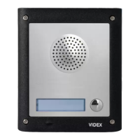
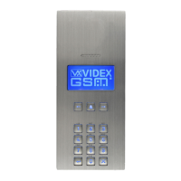
The 4000 Series IP video speaker unit module can be used with any VIDEX IP device or any computer using a specic MS-Windows Client or any
smartphone/tablet using a specic Android client. It is available in a 0, 1 or 2 button version but for installation with more than 2 call buttons can
be used in combination with the special interface module Art.4513 that enables the connection of up to 64 additional buttons using conventional
button expansion modules.
• Videx 4000 Series modular system;
• 10/100 Mbit Ethernet interface;
• Compatible with SIP protocol (it can be connected with VOIP switchboard systems);
• It recognizes DTMF tones complying with RFC2833 specication;
• In built web server to set operation parameters;
• Possibility to connect up to 66 call buttons (an interface module is required to which it is possible to connect standard expansion modules
from the 4000 Series);
• 2 dry contact relay outputs (C, NC, NO) with programmable operation times;
• 1 “active low” input for “push to exit” button;
• It is possible to set up to 10 IP addresses or SIP ID’s for each call button;
• Client to be used with a PC using MS Windows operating system;
• Client to be used with a tablet and smartphone using Android operation system;
• Firmware can be updated through a web server;
• A wide angle camera is also available.
TERMINALS
L
Not used
H
+12Vdc 12Vdc - 500mA Power supply input
0Vdc Power Supply Ground
GND Ground
PTE “Push to Exit” active low input
RX+ CAT5 cable Orange/white wire
RX– CAT5 cable Orange wire
TX+ CAT5 cable Green/white wire
TX– CAT5 cable Green wire
NO2 Relay 2 normally open contact
NC2 Relay 2 normally closed contact
C2 Relay 2 common contact
NO1 Relay 1 normally open contact
NC1 Relay 1 normally closed contact
C1 Relay 1 common contact
TERMINALS TO ART.4513
RX-RS-232 RS-232 Connection RX signal
TX-RS-232 RS-232 Connection TX signal
GND Ground
Art.4503 IP Video Speaker Unit Module
Connection