LEDS
Door open LED
Can be used to indicate the status of a door or gate. It re-
quires a switched 12Vdc connection to terminal “LD”.
Privacy ON/OFF LED
When the videophone is in stand-by, this LED signals
the privacy service status
(ON = service enabled, OFF = service disabled).
CONTROLS
SW1
Call tone volume switch
(3 levels).
PT1
Brightness control
(sliding wheel).
PT2
Hue adjustment trimmer
(rotate left to increase or right to decrease).
PT3
Contrast adjustment trimmer*
(rotate left to increase or right to decrease).
*Not available in some LCD versions.
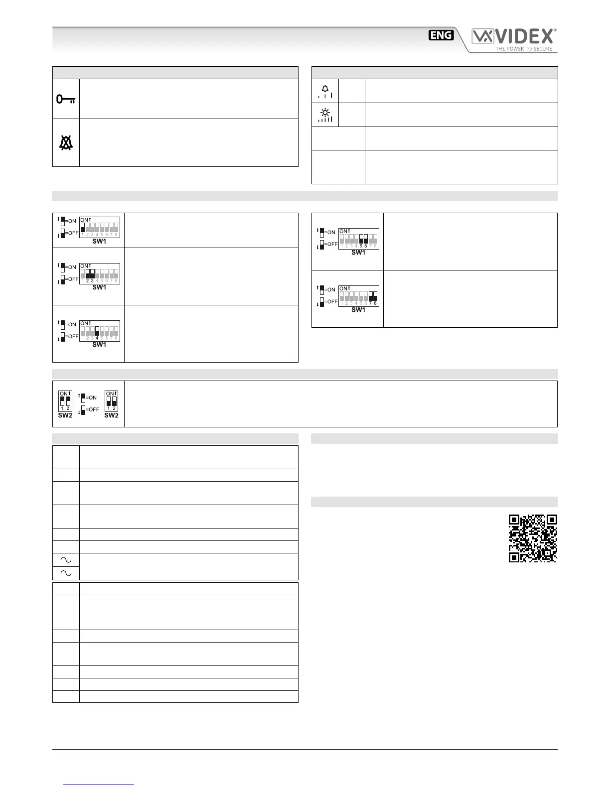
SETTINGS DIPSWITCH
The videophone setup is carried out by the 2 dip-switch banks.
Switches 1 Apartment Address
OFF 1
ON 2
Switches 2,3 Extension Address
OFF OFF 1
ON OFF 2
OFF ON 3
ON ON 4
Switch 4 Intercommunication
OFF Between videophones of the two
apartment
ON Between videophones in the
same apartment
Switches 5,6 Number of rings
OFF OFF 2
ON OFF 4
OFF ON 6
ON ON 8
Switches 7,8 Privacy duration time
OFF OFF 15 minutes
ON OFF 1 hours
OFF ON 4 hours
ON ON 8 hours
2 WAY DIPSWITCH SW2
The two way dip-switch adjusts the impedance of the video signal. The default setting is “ON” for both switches
(75 Ohm): when there are more videophones in parallel connection (without video distributor) both switches
must be “ON” only on the last videophone (looking at the connection order) while for all other videophones
both switches must be set to “OFF”.
CONNECTION TERMINALS SIGNALS
+V
20Vdc Input/Output (As input 16÷20Vdc 0,5A – as out-
put 20Vdc 0,5A max)
Ground reference for +V terminal.
1
Speech line output from handset’s microphone and data
signal (Approx. 12V in stand-by, 5V during a conversation)
2
Speech line input toward the handset’s loudspeaker (Ap-
prox. 12V in stand- by, approx. 3V during a conversation)
V1 Balanced video signal 1 sync.-
V2 Balanced video signal 2 sync.+
24Vac 1A max power input
LB Local call input (5V in standby, 0V to trigger)
SB
Service button (open collector) active low output. The
button goes active when the button is pressed (Open
Collector 24Vdc 100mA max)
LD 12Vdc input for door-open LED
2A
Speech line input toward the loudspeaker of the parallel tele-
phone (Approx. 12V in stand-by, 3V during a conversation)
3A Output switched ground for parallel telephone
4A Output call tone for parallel telephone
5A Input for door-open command from parallel telephone
TECHNICAL SPECIFICATION
Power Supply: Supplied by the BUS line, 20Vdc
Power consumption: Stand-by: 50mA Max
Operating: 200mA Max
Working Temperature: -10 +50 °C
MEMORY BOARD
This device is also available in the version with
memory board (Art.6256/VM).
If you have that version, please refer to the
“6200, 6300, 6400 and 6700 Series Memory
Board” user manual (in English and Italian) for
installation and use.
The manual is available for download: click/tap or scan the
QR code.
Art.6256 3.5" colour videophone
 Loading...