H
Fig. 5
2
1
Fig. 6
Fig. 7
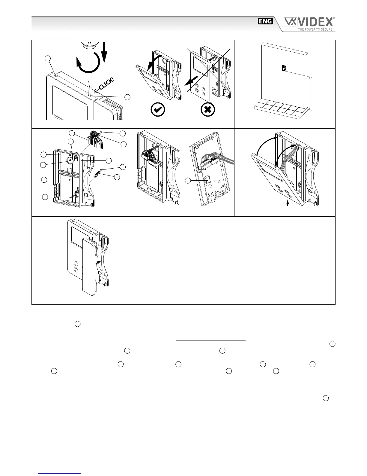
1. In order to install the videophone, it is necessary to remove the cover, which contains all the electronics, from the base: rstly
disconnect the handset from the videophone (by removing its plug from the videophone) then insert a 5.5mm at screw driv-
er into the clip
A
then rotate clockwise until you listen a “CLICK!”.
Repeat the same operation with the other clip as shown in Fig. 1.
2. Pull outwards the top part of the cover as shown in Fig. 2. Don’t pull the cover straight.
3. Put the base of the unit on the wall at approx 135cm from the nished oor (Fig. 3) to mark the points for the xing holes
B
(Fig. 4) remembering that the wires
E
(Fig. 4) must be fed through the hole
F
(Fig. 4). If you use the ush mounting box 503,
embed it into the wall vertically at approx. 140cm from the nished oor and the base.
4. Following Fig. 4, make the holes
B
, insert the wall plugs
C
and x the base with the screws
D
feeding the wires
E
into the
hole
F
. If you have used the box 503, x the base to the wall through the holes
G
using the screws
D
.
5. As shown in Fig. 5A, connect the wires to the removable terminals following the provided installation diagram. Connect the ter-
minal blocks to the electronics contained in the cover as shown in Fig. 5B. Reinsert the handset and test system before closing.
Note: Contrast and hue trimmers can be adjusted only if the videophone is open. Note while testing the system, it is
advisable to hold the cover with your hand closing manually the hook switch of the handset (see Fig. 5B reference
H
).
6. Once testing is complete and all the necessary adjustments are made, disconnect the handset from the cover and close the unit
as shown in Fig. 6: rst hook it on the bottom then push in the top until you hear a “CLICK!”.
7. Reconnect the handset and hang it as shown in Fig. 7.
 Loading...