OPERAZIONI PRELIMINARI
• Nella verisone 13F1 il dip switch 2 andrà posizionato su ON. Nella
verisone 13F2 il dip 2 andrà posizionato su OFF. Nel caso di utilizzo
della versione audio 13F1 con una TLC esterna tipo TVCC il dip switch 2
dovrà essere posizionato su OFF (fig. 4).
• Le unità elettroniche nelle versioni 13F1/13F2 vengono fornite con i
Dip Switch settati con identificativo ID = 1 (Master). Negli impianti con
una sola targa l’identificativo ID deve essere MASTER. Lasciando il dip
switch 1 su ON, i dip switch 3 e 4 non hanno valenza (fig.4).
• Negli impianti dove sono presenti più targhe, si dovrà definire una targa
MASTER e le altre SLAVE. Nella prima unità elettronica lasciare il dip
switch 1 nella posizione ON, nelle altre unità elettroniche il dip switch 1
dovrà essere spostato su OFF e dovranno essere configurati i dip switch
3 e 4 riferendosi a fig. 4. Ogni unità elettronica dovrà avere un numero
identificativo ID univoco.
Nel caso di configurazione dell’ identificativo ID con PC e software
di programmazione SaveProg, la configurazione avrà priorità sulla
configurazione manuale.
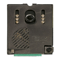
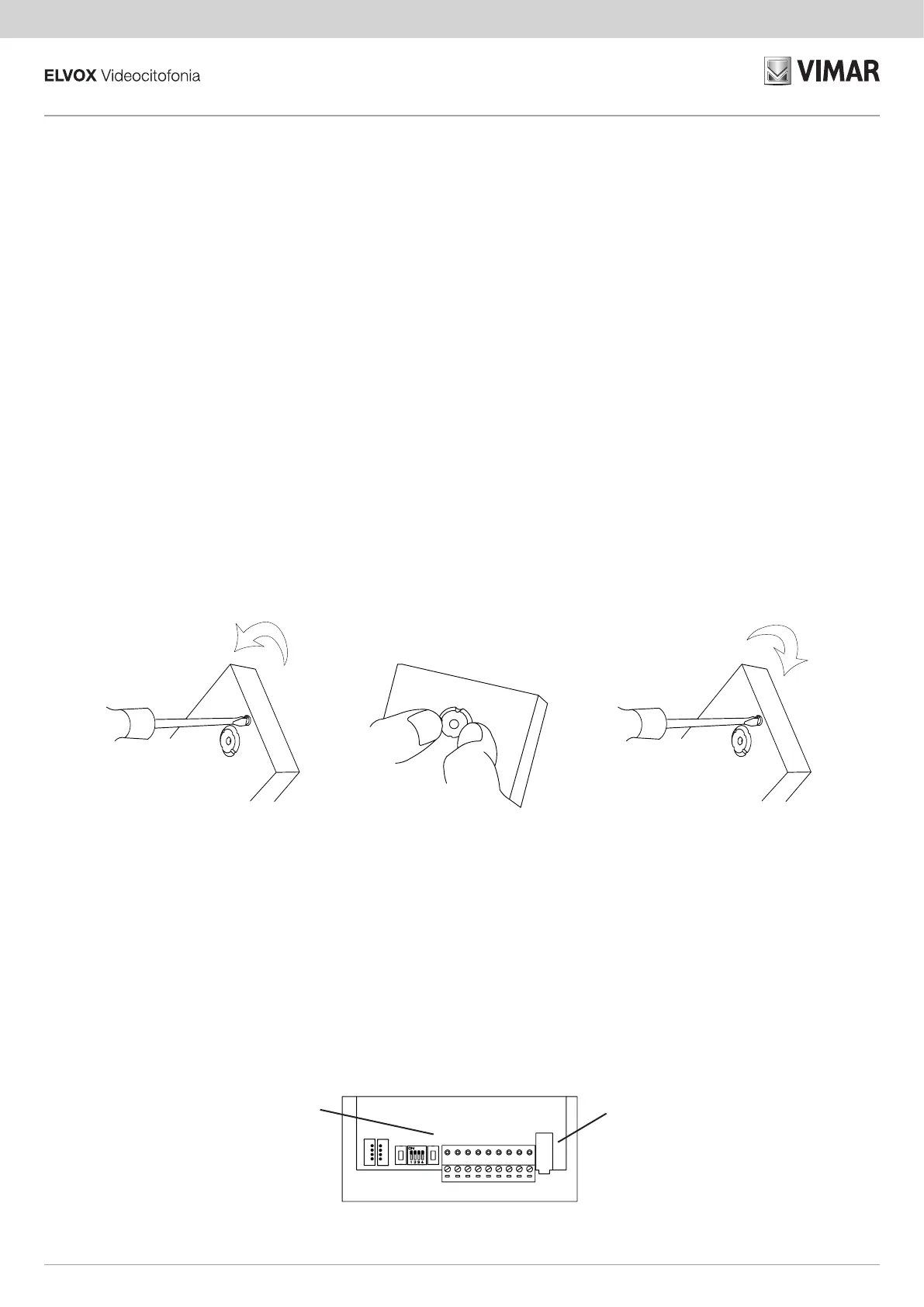
ORIENTAMENTO OBIETTIVO (PRESENTE 13F2)
L’obbiettivo della telecamera può essere regolato manualmente (fig.5)
sull’asse verticale e orizzontale per adattare l’ angolo di ripresa alle es-
igenze.
1. Allentare la vite posta sopra dell’obiettivo
2. Ruotare lo stesso nella direzione voluta
3. Fissare la vite.
g. 5
PRELIMINARY PROCEDURES
• On version 13F1 dip switch 2 will be ON. On version 13F2 dip switch 2 will
be OFF. If using audio version 13F1 with an external CCTV-type camera
dip switch 2 must be OFF (fig. 4).
• On versions 13F1/13F2 the electronic units are supplied with the Dip
Switches set with ID = 1 (Master). In systems with a single entrance
panel, the ID must be MASTER. Leaving dip switch 1 ON, dip switches
3 and 4 have no effect (fig.4).
• If there are multiple entrance panels in the system, a MASTER panel
should be established and the others designated as SLAVE. On the first
electronic unit leave dip switch 1 ON, on the other electronic units dip
switch 1 must be moved to OFF and dip switches 3 and 4 must be con-
figured with reference to fig. 4. Each electronic unit must have a single
ID number.
When configuring the ID with a PC and the SaveProg programming
software, the configuration will have priority over manual configura-
tion.
LENS ADJUSTMENT (ON 13F2)
The camera lens can be adjusted manually (fig.5) on the horizontal and
vertical axis to adjust the angle of view to suit your needs.
1. Loosen the screw above the lens
2. Turn it in the desired direction
3. Fasten the screw.
TASTI PER CONFIGURAZIONE MANUALE DEI PARAMETRI
Il tasto PRG viene utilizzato per la conferma del dato selezionato. Il tasto
P1 viene utilizzato per procedere con la fase successiva di regolazione e
dopo l’ultima regolazione, il tasto P1 permette di uscire dalla modalità di
configurazione.
Alla fase di configurazione, si accede premendo e mantenendo premuto
il tasto PRG, premere e mantenere premuto anche il tasto P1 (circa 2s)
fino all’emissione di una nota dall’altoparlante dell’unità elettronica. Dopo
avere avuto accesso alla procedura di configurazione, possono essere
configurati i parametri riportati nel capitolo ”CONFIGURAZIONE manuale
dei PARAMETRI”.
BUTTONS FOR MANUAL CONFIGURATION OF PARAMETERS
Button PRG is used to confirm the selected data. Button P1 is used to
proceed with the next phase of adjustment and after the last adjustment,
button P1 is used to exit configuration mode.
In the configuration phase, accessed by pressing and holding down
button PRG, press and hold down button P1 too (approximately 2s) until
the electronic unit’s speaker beeps. After accessing the configuration
procedure , you can configure the parameters given in the ”MANUAL
PARAMETER CONFIGURATION” chapter.
P1PRG
g. 6
4
13F1 - 13F2
 Loading...