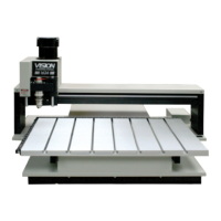
Table Descriptions 15
© 2013 Vision Engraving & Routing Systems
16 and 24 Series Engravers Carriage Descriptions
(Refer to the diagram below)
1. Z-Axis Stepper Motor. The small motor under the carriage cover that provides the spindle up and
down motion of the spindle during the engraving process.
2. Spindle Assembly. The spindle mounted in its block; includes a pulley, housing, micrometer,
retainer ring, nose cone and associated hardware. The spindle assembly moves up and down along a
linear bearing, which attaches to the face of the carriage assembly.
3. Spindle Block. Houses the spindle assembly.
4. Z-Axis Leadscrew. The threaded screw which raises and lowers the spindle during the engraving
process.
5. Engraving Motor Belt. Drive belt connecting the engraving motor to the spindle pulley.
Typical 16 and 24 Series Carriage Diagram

