12 | Signals11 | Assembly
Assembly
A LED is installed on the equipment that signals the operating state of the equipment. The following table provides an overview of the
dierent states of the LED and explains their meaning:
Signals
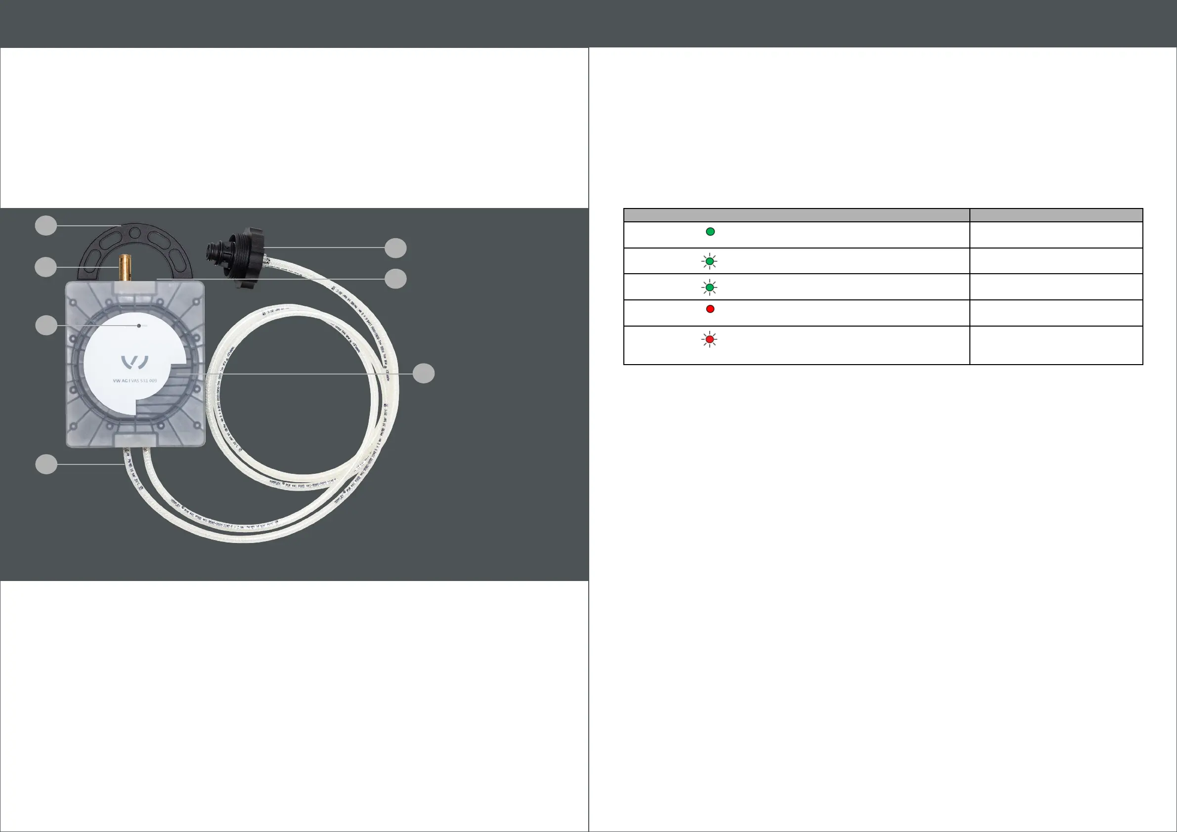
The following illustration shows the conguration of the equipment:
2
6
5
1 Mountings
2 Safety valve
3 LED red/green
4 2 hoses, permanently connected to VAS 531 009 and the coolant adapter
5 Coolant adapter
6 Mini USB port
7 Inspection window (for intake coolant)
LED state Meaning
Green
Constantly lit
The system is ready to start a measurement
Green
Slowly lashing
Measuring process active
Green
Quick lashing
Pump activated
Red
Constantly lit
CO coolant tester is not in normal position
Red
Flashing
A malfunction occurred. In this case, the software
displays an error message which shows more
detailed information
7
1
3
4
 Loading...