39
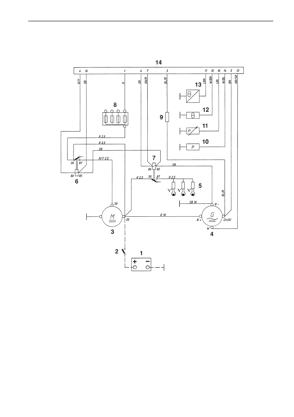
Wiring Diagrams
Engine 2010, 2020, 2030, 2040
Cable color
BL = Blue OR = Orange
LBL = Light-blue R = Red
BN = Brown SB = Black
LBN = Light-brown W = White
GN = Green Y = Yellow
GR = Gray
1. Battery
2. Main switch
3. Starter motor
4. Generator
5. Glow plugs. MD2010: x 2. Others x 3.
6. Starter relay
7. Glow plug relay
8. Fuses, max. 15A (+)
9. Excitation resistor
10. Oil pressure switch, engine
11. Oil pressure sensor
12. Coolant temperature switch
13. Engine coolant temperature sensor
14. Connector, 16-pin.
Cable areas in mm
2
are indicated after the color codes in
the wiring diagrams.
Areas not indicated = 1.0 mm
2
.
A broken line indicates a non-Volvo Penta cable.
7738231 - Downloaded from www.volvopenta.com 29/03/2009 14:51:17
 Loading...