11
10. Voltmeter
The voltmeter shows the voltage in the starter battery
circuit. The voltage should be about 14V during opera-
tion. The voltage is about 12V when the engine is off.
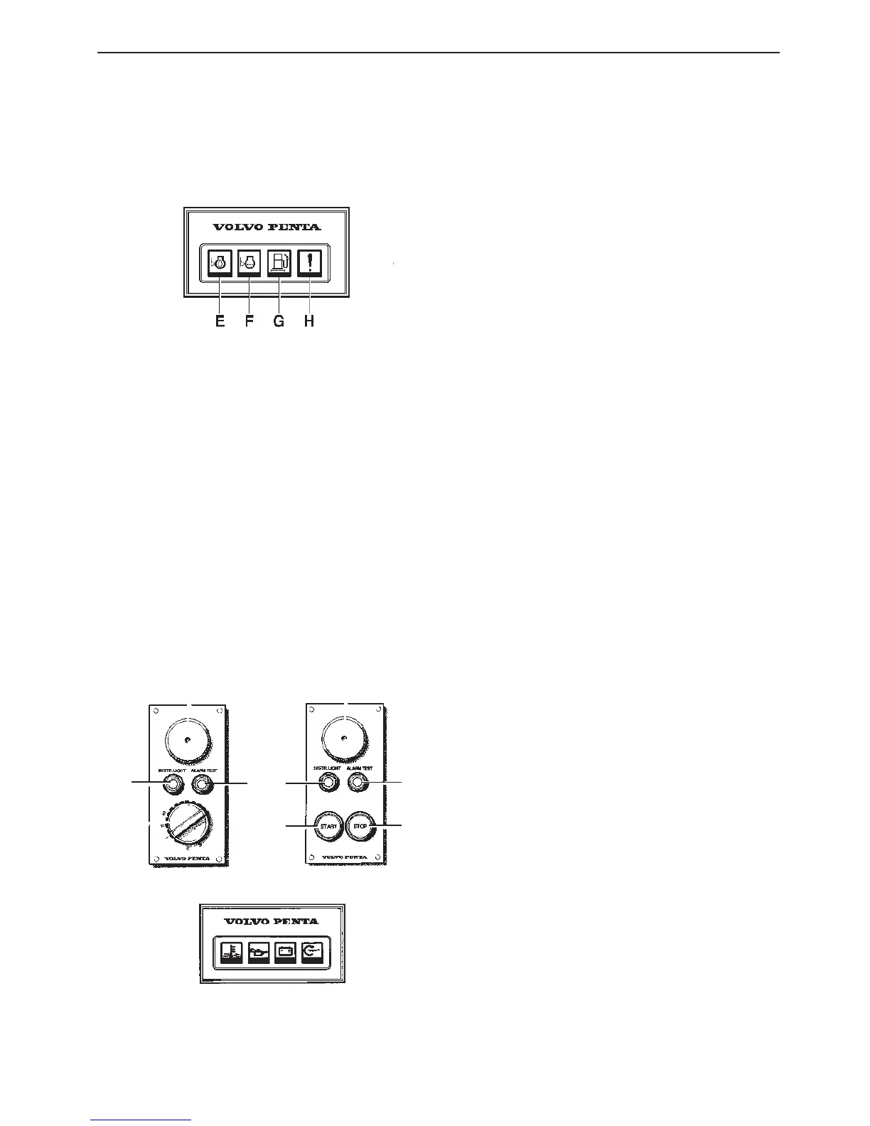
Supplementary warning display
The display has four “windows”. If the acoustic alarm
comes on, one of the windows starts to blink (red) to
show the cause of the alarm.
E. Lubricating oil level too low.* Top up with oil to the
correct level before start.
F. Coolant level too low.* Top up with coolant to the
correct level before start.
G. Water in extra fuel pre-filter.** Drain the water in
the filter.
H. Extra alarm for monitoring any optional function.***
* Warning function only when engine is stopped and key
switch is in position I
** Warning function both when engine is stopped and running.
Key switch in position I
*** Warning function only when engine is running. Key switch in
position I
Instrument sets
The instrumentation is also supplied separately in sets.
These sets include the following three smaller panels
for starting and stopping and for utilising the alarm
functions.
Control panel for pilot house (main panel)
Control panel for alt. operating position
N.B.: The key switch in the pilot house control panel
must be in position I (operating position) for starting to
be carried out from the alt. operating position. The pre-
heating can only be engaged via the key switch on the
panel in the pilot house.
11. Starter button. The starter motor is engaged when
this button is pressed. Release the button as soon
as the engine has started.
12. Stop button. The stop solenoid is engaged when
this button is pressed.
11
12
5
6
5
6
 Loading...