12
Installation
SIP contemporary lobby/1-line/2-line - S2100/S2210/S2220
CAUTION:
Use only the supplied Cat-5 network cable. Cat-5 network cable is not designed for use in any other IT devices. Misuse of Cat-5 network cable on
your other IT devices shall be prohibited. To order a replacement, visit our website at www.vtechhotelphones.com or call 1-888-907-2007.
Telephone base installation
This telephone can be adapted to desktop use or mount on a standard telephone wall plate.
Installation option - desktop position
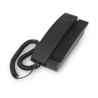
Turn the telephone base over with the bottom side facing up. Connect the coiled handset cord to the telephone base.
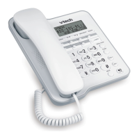
Insert the lower tabs of the mounting bracket into the lower grooves of the telephone base. Press the upper tabs of the mounting
bracket and then push into the center of the telephone base until it locks into place.
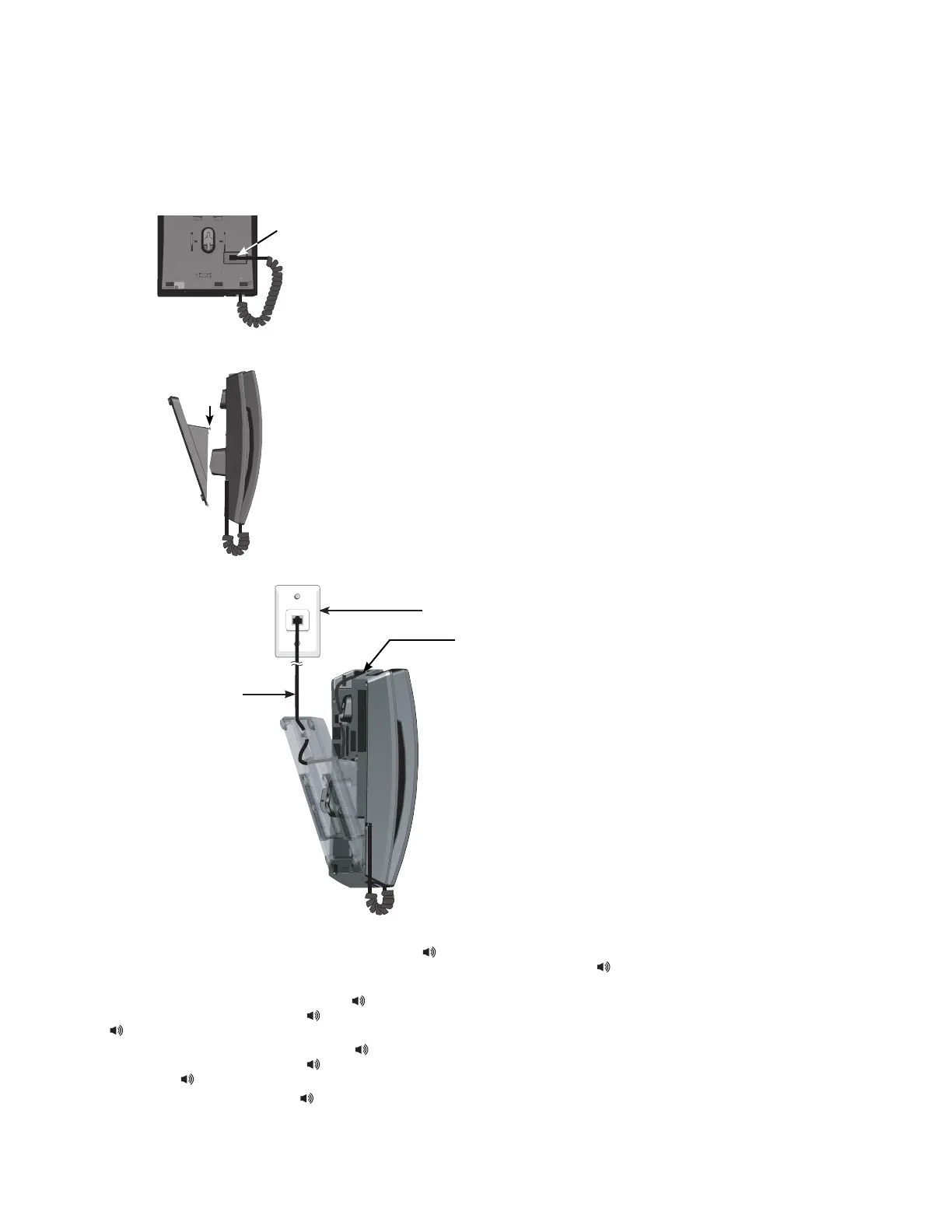
Plug the Cat-5 network cable into the RJ-45 LAN port on the telephone base and the network wall jack.
Once installed, the telephone begins a four-step initialization and system registration process.
For S2100: (1) The MUTE key cavity LED and the /SPEAKER key cavity LED turn on and then go off. (2) The MUTE key
cavity LED ashes. (3) The MUTE key cavity LED stops ashing and then the /SPEAKER key cavity LED ashes.
(4) Both LEDs illuminate for 500ms when initialization and system registration are successful.
For S2210: (1) The MUTE key and the /SPEAKER key turn on and then go off. (2) The MUTE key ashes. (3) The MUTE
key stops ashing and then the /SPEAKER key ashes. (4) The MESSAGE WAITING LED, LINE, MUTE and
/SPEAKER illuminate for 500ms when initialization and system registration are successful.
For S2220: (1) The MUTE key and the /SPEAKER key turn on and then go off. (2) The MUTE key ashes. (3) The MUTE
key stops ashing and then the /SPEAKER key ashes. (4) The MESSAGE WAITING LED, LINE 1, LINE 2, CONF,
MUTE and /SPEAKER illuminate for 500ms when initialization and system registration are successful.
If the system registration fails, the /SPEAKER key blinks twice every second. To reset, disconnect the Cat-5 network cable
from the network wall jack with Power over Ethernet (PoE) and connect it back again.
1.
2.
3.
4.
•
•
•
Coiled handset cord jack
Cat-5 network cable
RJ-45 LAN port
Network wall jack with Power over Ethernet (PoE)
 Loading...