Maintenance G/GS 5.6A
wc_tx000164gb.fm 36
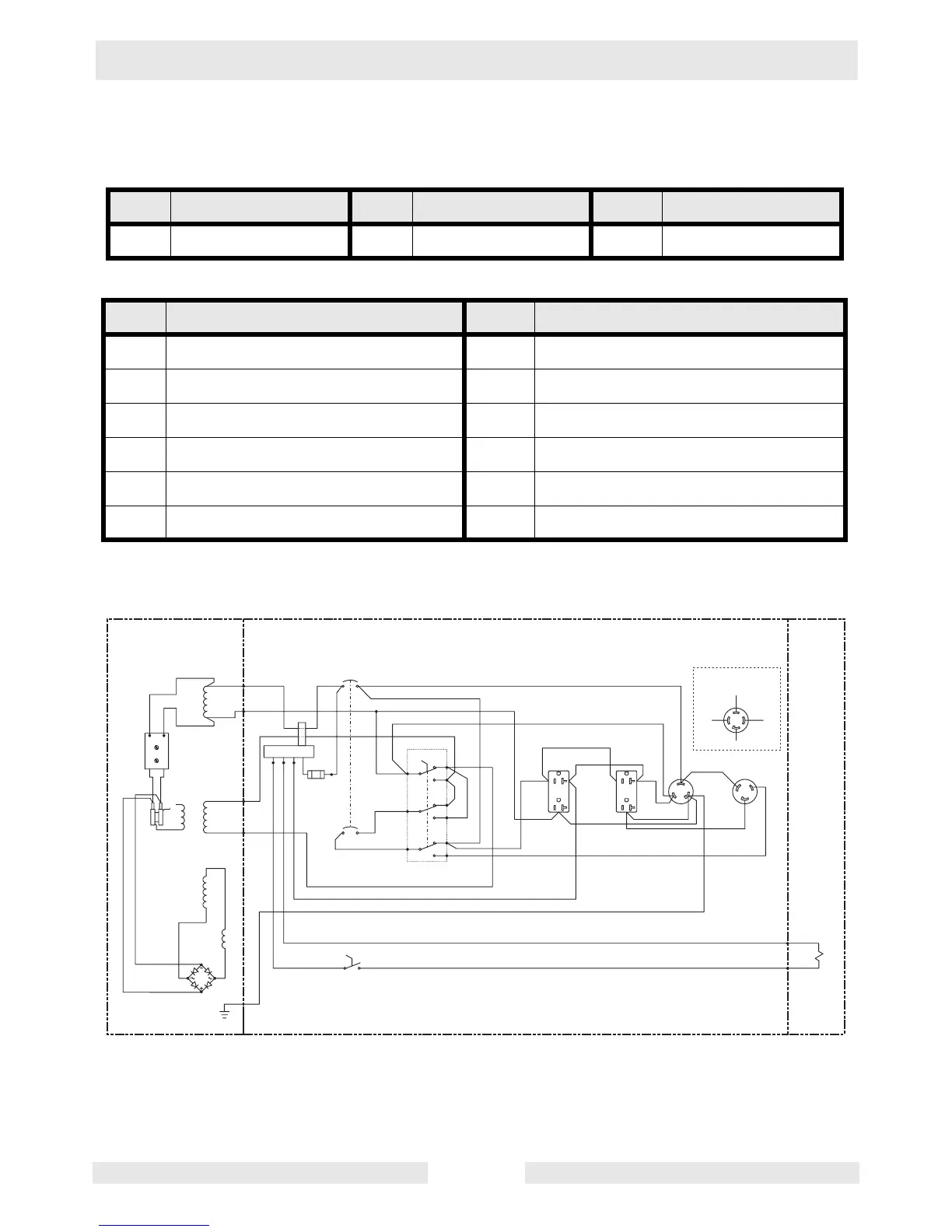
5.14 Electrical Schematic
See Graphic: wc_gr000556
Ref. Description Ref. Description Ref. Description
A Generator B Control Box C Engine
Ref. Description Ref. Description
1. Main Stator Winding 7. Auto Idle
2. Automatic Voltage Regulator 8. 1 Amp Fuse
3. Rotor Winding 9. Auto Idle Switch
4. Main Stator Winding 10. 120/240V 30A Kit*
5. Auxiliary Stator Winding 11. Electromagnet
6. Choke
*W/B (Extra wire included in kit. Terminate at 120V 30A receptacle.)
w c _ g r 0 0 0 5 5 6
G / W
R / W
B / W
B / W
G / W
2
G / R
G / Y
R / W
L / Y
W / O r
1
L / G
B / R
G / L
W / R
R / Y
1
3
2
1 2 0 / 2 4 0 V
W / G
R / L
5
4
7
8
9
R / G
B / G
G / Y
R / B
B / O r
6
B / L
R
W
R
W
1
2
4
3
2
L 2
B
F 2
S T A B .
R
F 1
V O L T A G E
L 1
L
L
3
4
F 1
Z 1
B r
Z 1
Z 3
Z 3
Z 2
Z 2
L / B
l
B / Y
1 2 0 V A C
2 0 A
1 2 0 V A C
2 0 A
1 2 0 V A C
3 0 A
2 4 0 V A C
2 0 A
F 2
W / Y
W / L
B r
A
1
2
3 4
5
6
7
8
9
O
B
1 0
C
1 1
 Loading...