G 2.5A Maintenance
wc_tx000170gb.fm 31
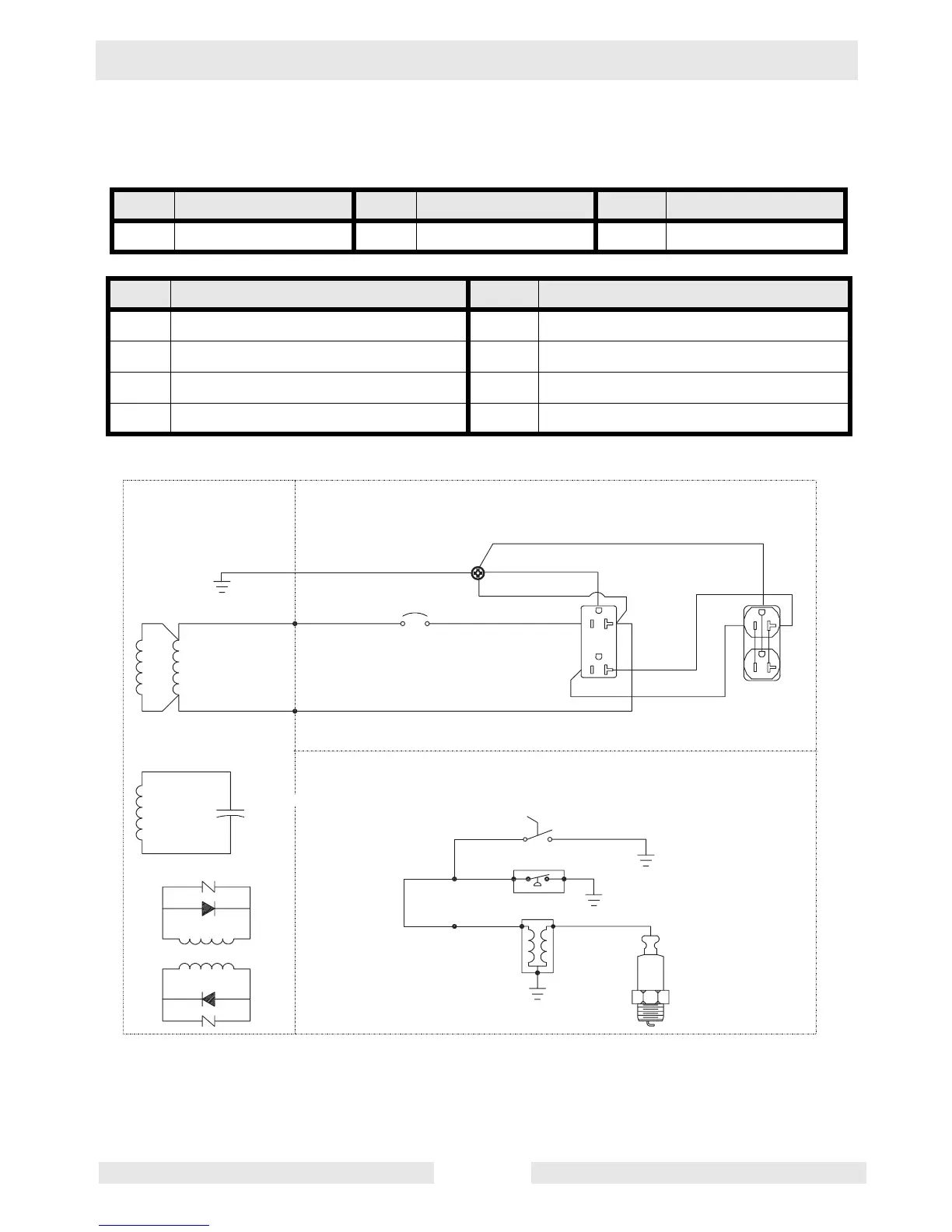
5.13 Wiring Schematic
See Graphic: wc_gr000767
Ref. Description Ref. Description Ref. Description
A Generator B Control Box C Engine
Ref. Description Ref. Description
1. Main Windings 5. Ignition Switch
2. Aux Winding 6. Oil Level Switch
3. Capacitor 25 µF 400 V 7. Coil
4. Rotor Windings
w c _ g r 0 0 0 7 6 7
B
G
W / Y
G / Y
B / R
2 0 A
B / Y
1 2 0 V A C
B
Y
G / Y
2 0 A
2 0 A
1 2 0 V A C
B
)
R
1
W
R
W
2
3
B
4
B
2 5 u F
4 0 0 V
G / W
G
*
+
1
2
3
4
5
7
6
0
1

 Loading...