When working outdoors:
Vapors containing solvents may not be allowed to
blow toward the unit.
Note the direction of the wind.
Set the unit up in such a way that vapors containing
solvents do not reach the unit and build up there.
A minimum distance of 5 m between the unit and
spray gun is to be maintained.
U Ventilation when spraying in rooms
Adequate ventilation must be guaranteed for the removal of the
solvent vapors.
U Suction installations
Thesearetobeset-upbytheuseroftheunitaccordingtolocal
regulations.
U Earthing of the object
The object to be coated must be earthed.
U Cleaning units with solvents
When cleaning the unit with solvents, the solvent
should never be sprayed or pumped back into a
container with a small opening (bunghole). An
explosive gas/air mixture can be produced. The
container must be earthed.
U Cleaning the unit
Danger of short circuit through penetrating water!
Never spray down the unit with high-pressure or
high-pressure steam cleaners.
U Work or repairs on the electrical
equipment
Onlyhavethisworkcarriedoutbyaqualiedelectrician.Noliability
will be taken for incorrect installation.
U Working on electrical components
Remove the mains plug from the socket for all such works.
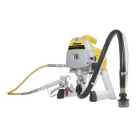
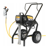
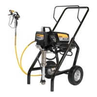
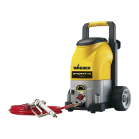
Components and Description
The shipping carton for your painting system contains the following:
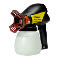
• Spraygunwithtwolters(MingunandoneXS-SandoneMseparate) •Oneaxle,twoaxleplatesandfourscrews
• Twowheelassemblies(including2metalcoversand2plasticcovers) •Spraytipassembly
• 7.5m,1/4”internaldiameterpressurehose •Oneinletvalvepushertool
• Anassemblyaid(positionedbeneaththehopper) •Instructionmanual
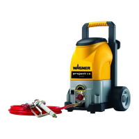
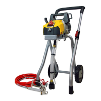
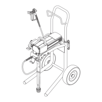
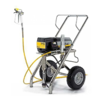
Figure 1 - Controls and Functions
(further, detailed descriptions of the individual items can be found in the relevant section of the operating
instructions)
Item Component Description
A) Extendable handle .......................Thehandleextendsforeasytransportandstorage.
B) Removable Hopper ......................Thehoppercanberemovedforeasyemptyingandcleaning.Itcanberemovedwhenemptyor
when lled with material. Do not exceed 9.5 liters. The cover of the hopper does not seal, therefore
material can emerge from the upper container if too much material is put in or the hopper tips up.
C) ON/OFFSwitch ............................TheON/OFFswitchturnsthepowertothesprayeronando(O=OFF,l=ON).
D) PRIME/SPRAYKnob ....................ThePRIME/SPRAYknobdirectsuidtothesprayhosewhensettoSPRAYorthereturntubewhenset
to PRIME. The arrows on the PRIME/SPRAY knob shows the rotation directions for PRIME and SPRAY.
ThePRIME/SPRAYknobisalsousedtorelievepressurebuiltupinthesprayhose(seePressureRelief
Procedure).
E) Project Control ...............................ProjectControlfunctions:Prime,Clean/Roll,Spray1-MAXSpray.
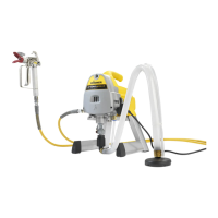
F) Return Tube ....................................Fluid is sent back out through the return tube to the original container when PRIME/SPRAY knob is in
PRIME position.
G) Handle lock .....................................The handle lock allows the extendable handle to extend or contract.
H) SprayGun ........................................Forapplicationofthecoatingmaterialandregulationofthepumpcapacity.
I) SprayHose ......................................Thesprayhoseconnectstheguntothepump.
12
Project115-SafetyInformation
 Loading...