Page 36
Table 7 Electrical Installation Specification
NOTE: The incoming power supply must be connected via an isolating switch with a
minimum breaking gap of 3mm. Cable cross sectional areas should be calculated
according to the current at full load together with the on-site conditions and the cable
length between the heat pump and the consumer unit, the above table lists minimum
recommendations only.
* This unit features an integrated immersion heater which if used requires an additional 14Amp supply.
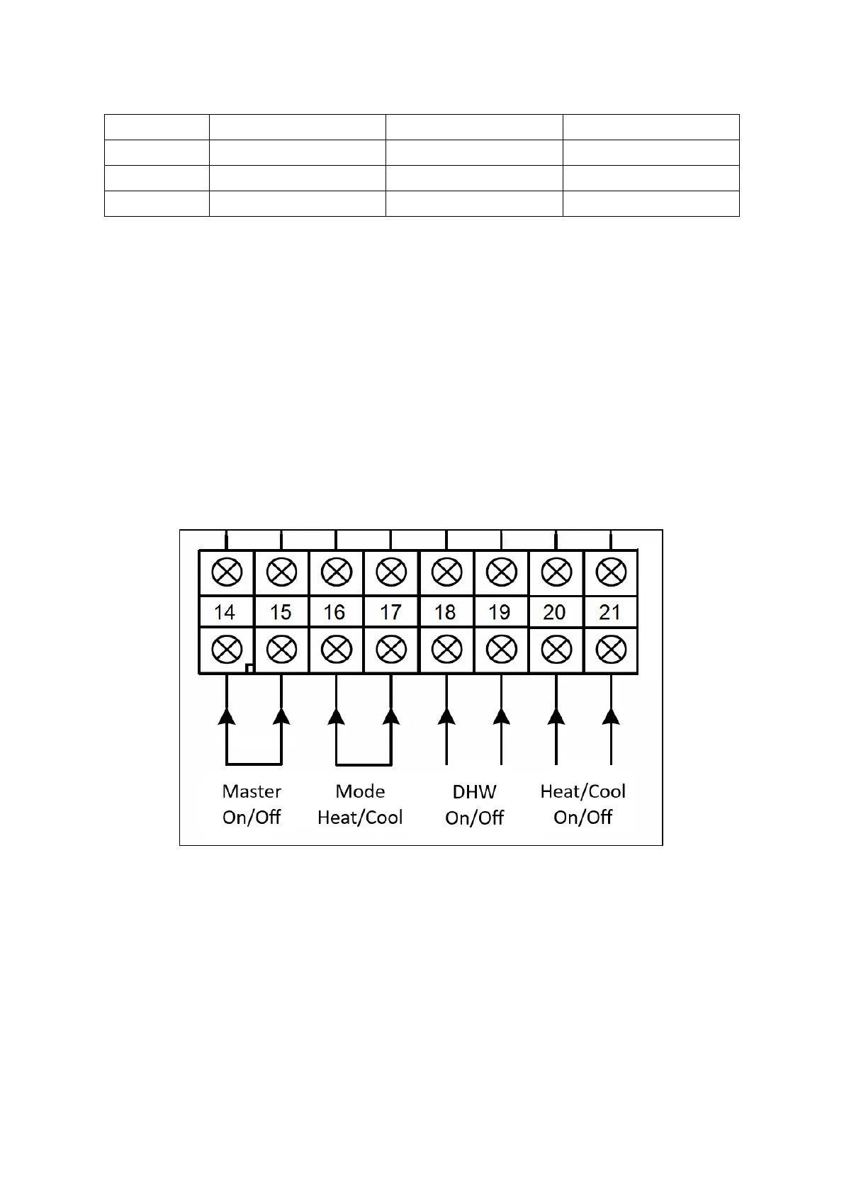
3.10.2 Digital Inputs
The unit can also be controlled remotely from an external controller such as a timeclock or room
thermostat instead of the internal timeclock. To enable remote control, parameter H02 must be
changed from ‘Master’ to ‘Slave’. This will activate the digital input connections in the installers
wiring enclosure. These connections are all ‘volt free’ and therefore no voltage should be
connected into any of them, they are enabled by connecting the relevant terminals together.
Figure 30 Installer’s Digital Input Connections (AS01 & AS03 units)
 Loading...