2
1
⁄2" – 3"
*
Figure 3
2
NOTICE
Shutoff Valves: When shutoff valves are removed and re as sem-
bly is necessary, the shutoff valve with the test cock is to be
mount ed on the inlet side of the backflow preventer.
A. The assembly should always be installed in an accessible location
to facilitate testing and servicing. Check the state and local
codes to ensure that the backflow preventer is installed in
compliance, such as the proper height above the ground.
B. Watts recommends that a strainer be installed ahead of the
assembly to protect the internal components from unnecessary
fouling.
CAUTION
!
Do not add a strainer when the backflow preventer is installed on
seldom-used water lines, such as fire sprinkler lines or other lines
called upon only during emergencies.
Start Up: The down stream shutoff should be closed. Open the
upstream shutoff slowly and fill the valve. When the valve is filled,
open the downstream shutoff slowly and fill the water supply sys-
tem. This is necessary to avoid water hammer or shock damage.
C. Water discharge from the relief valve should be vented in ac cor-
dance with code requirements. The relief valve should never be
solidly piped into a drainage ditch, sewer, or sump. The discharge
should be terminated approximately 12" above the ground or
through an air gap piped to a floor drain.
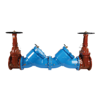
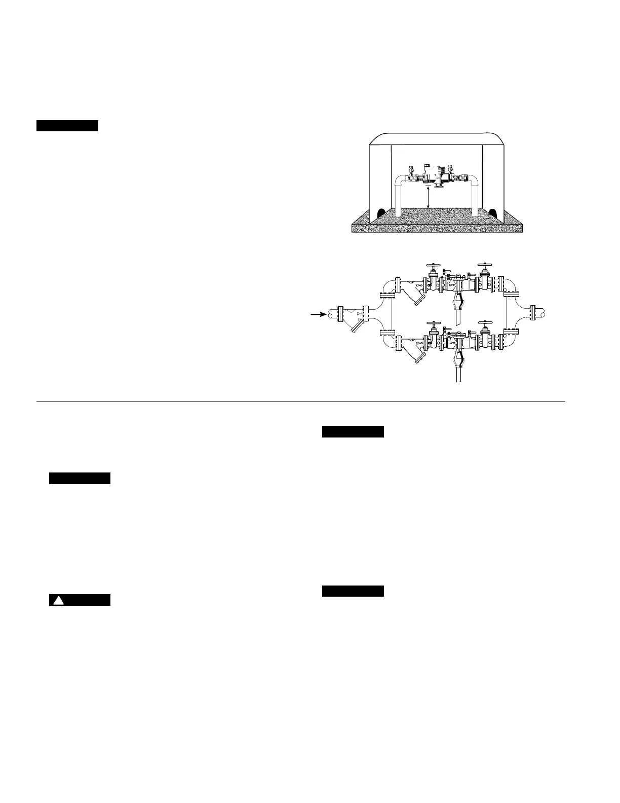
Parallel
Two or more smaller-sized assemblies can be piped in parallel (when
approved) to serve a large supply pipe main, as shown in Figure 3.
This type of installation is employed where in creased capacity is need-
ed beyond that provided by a single valve and permits testing or ser-
vicing of an individual valve without shutting down the complete line.
The number of assemblies used in par al lel should be determined
by the en gi neer’s judgment based on the operating con di tions of a
specific installation.
For parallel valve installations, the total capacity of the assemblies
should equal or exceed that required by the system.
Outside
In an area where freezing conditions do not occur, the assembly
can be installed outside. The most sat is fac to ry in stal la tion is above
ground; thus, the assembly should be in stalled in this manner.
Backflow preventers should not be installed in pits unless approved
by local codes. In such cases, a modified pit installation is preferred.
Figure 2
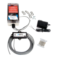
WattsBox
12"
NOTICE
In an area where freezing conditions can occur, the assembly
should be installed above ground in an insulated enclosure, as
shown in Figure 2. (For more information, download the ES-WB
specification at watts.com.)
The assembly must be installed in an ac ces si ble location to facilitate
testing and ser vic ing. A discharge line should be piped from the air
gap at the relief valve con nec tion to ensure there is adequate drain-
age. Never pipe the discharge line directly into a drainage ditch,
sewer, or sump. Never install the assembly where any part of the
unit could become submerged in standing water.
Annual Inspection
Annual inspection of all water system safety and control valves is
required and necessary. Regular inspection, testing, and cleaning
assures maximum life and proper product function.
NOTICE
Relief Valve Discharge Rates
The installation of an air gap with the drain line terminating above
a floor drain handles any normal discharge or nuisance spitting
through the relief valve. However, floor drain size may need to be
designed to prevent water damage caused by a cat a stroph ic fail-
ure condition. See Figure 4 for maximum relief valve discharge
rates, size, and capacity of typical floor drains.
Do not reduce the size of the drain line from the air gap fitting.
Pipe full line size.
D. After initial installation, a discharge from the relief valve opening
may occur due to inadequate initial flushing of pipe lines to elimi-
nate dirt and pipe compounds. If flush ing does not clear, remove
the first check valve and clean thoroughly.
NOTICE
Periodic relief valve discharge may occur on dead end service
applications, such as boiler feed lines or cooling tower makeup
lines due to fluctuating supply pressure during a static or no flow
condition. To avoid this discharge, install a spring-loaded rubber
seated check valve ahead of the backflow assembly to “lock-in
”
the downstream pressure.
E. Backflow preventers should never be placed in pits unless ab so-
lute ly necessary and then only when and as approved by local
codes. In such cases, provision should be made to always vent
above flood level or for a pit drain to ensure an adequate air gap
below the relief port.
 Loading...