Marine heating system Installation Instructions
© Webasto Global Comfort Solutions
®
13
6.2 Intake hose
• Use is optional, not mandatory.
• Drill a Ø 5 mm condensation opening in the downward line from the heater and/or use a
separate condensation drain, see illustration.
• Fit a cap over the end of the hose as a protection against ingress.
• Air intake arrangement: cannot be blocked by objects.
• Intake hose as short as possible. Permissible intake length: see device-specific installation
instructions.
• Secure the intake hose: with hose clamps to at the heater intake hoses and with pipe clamps
or cable ties to fixed fittings.
• Recommendation: Use intake silencers (intake noise). Supplied with Air Top heating
systems. Otherwise: for suitable silencers see the parts catalog.
• Pay attention, if the metering pump cable is fed through the intake pipes: avoid pinching the
intake hose during assembly. Do not use metal intake hoses.
• Route the hose so that it is kink free.
7 Fuel supply
• During installation comply with national or local directives. If necessary, ask your local
authorized Webasto
®
Partner.
• Protect the boat hull/construction in the vicinity of the heater from the effects of
heat/contamination by fuel/oil.
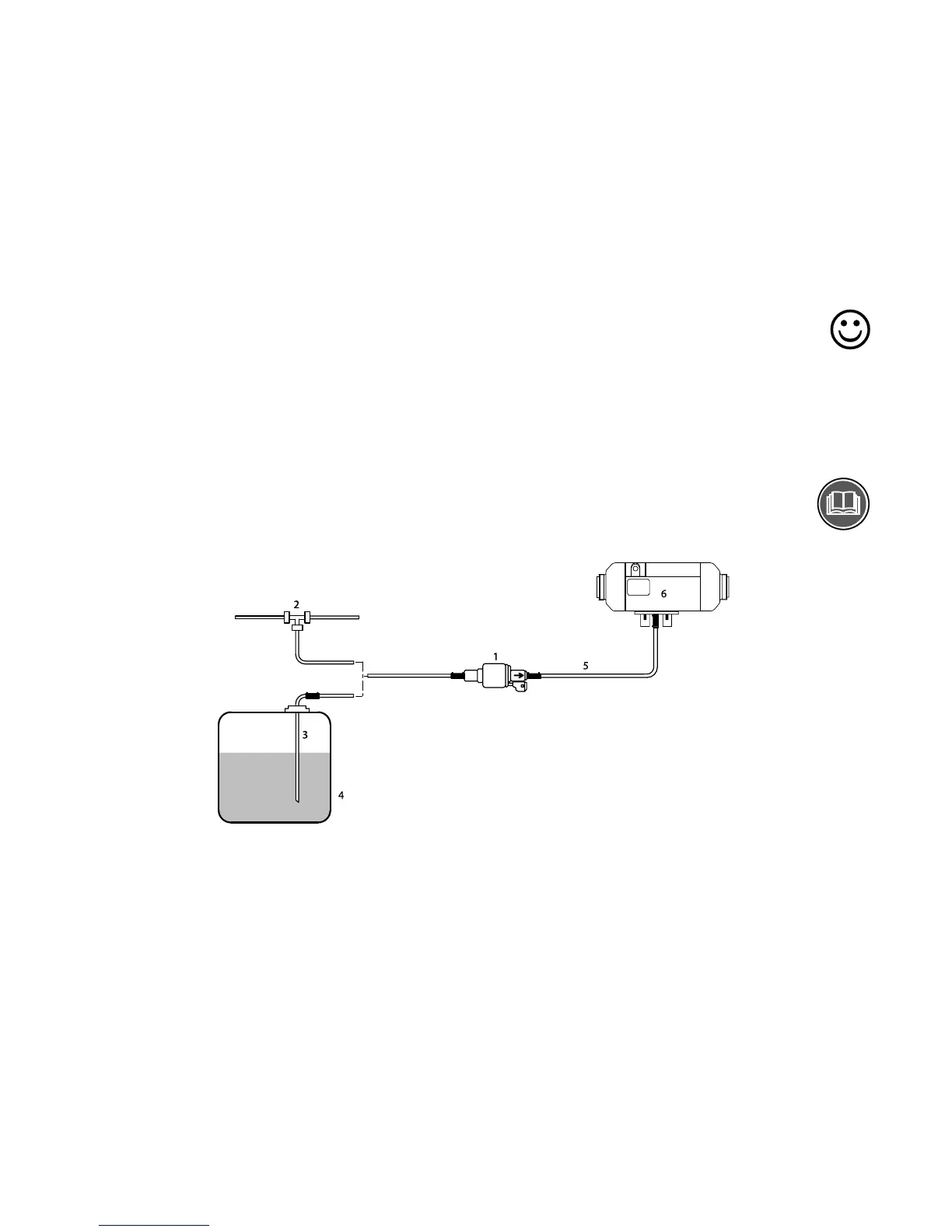
Example Air Top
®
heater fuel supply
1) Metering pump; 2) Fuel inlet; 3) Tank inlet; 4) Tank; 5) Fuel line; 6) Heater
7.1 Pipe lengths and lifting height
Observe the maximum permissible fuel intake height and/or lifting height for the dosing pump during
installation. Lengths: see device-specific installation instructions.
Example of the lifting heights for Air Top
®
, Thermo Top C
®
, Thermo 90ST
®
heating systems:
• Metering pump: Installation max. 500 mm below the tank surface level.
• Total intake length (A+B) < 2 m.
• C+D at pump pressure side < 6 m.
• Total lifting height D < 3 m.
 Loading...


