Page 18 Installation / Canadian InstallationsJB Manual
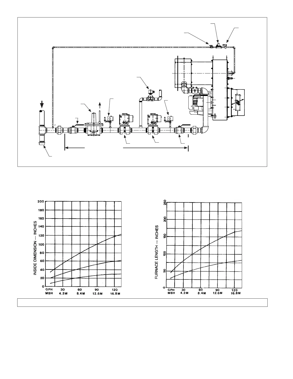
Drip Leg
Manual Gas
Shutoff Valve
Gas Pressure
Regulator
Low Gas
Pressure
Switch
Shutoff
Valve
Shutoff
Valve
High Gas
Pressure
Switch
Normally
open vent
valve
Leak Test
Valve
Pilot Gas
Pressure
Regulator
Pilot Solenoid
Valve
Pilot
Shutoff
Valve
Figure C-1
Typical Gas Piping
Gas Supply
Burner
If applicable, Webster
supplied gas train
D. SPECIAL INSTRUCTIONS FOR CANADIAN INSTALLATIONS
1. The installation of a burner shall be in accordance with
the regulations of the provincial installation requirements,
or in their absence, the following shall govern:
Gas Burners--CGAB149.1 and CGAB149.2
Oil Burners--CSA Standard B139
Authorities having jurisdiction should be consulted before
installations are made.
2. All electrical wiring shall be done in accordance with
Chart C-2 Chart C-3
FURNACE DIAMETER - INCHES
Width
Height - Floor to Center of Burner
Length
Length
Diameter
TYPICAL COMBUSTION CHAMBER SIZE
FOR FIREBOX BOILERS, WATERTUBE &
CAST IRON SECTIONAL TYPES
TYPICAL COMBUSTION CHAMBER SIZE
FOR SCOTCH MARINE FIRETUBE BOILERS
the Canadian Electrical Code, Part I.
3. The installer shall identify (label) the main electrical
power disconnect and the manual shut-off valve on the
gas and/or oil supply drop-line to the burner.
4. Oil and gas burning equipment shall be connected to
fl ues having suffi cient draft at all times, to assure safe
and proper operation of the burner.
 Loading...
