Page 28 Initial Settings JB Manual
G. INITIAL SETTINGS
The burner will be set at the factory for normal ini-
tial settings. These are only rough settings that
must be adjusted at startup to match the furnace,
fuel pressure and environment of the specifi c ap-
plication. These general settings are covered in
this chapter as a means of checking the burner
(linkage and settings can move in shipment) or
readjusting the burner if the settings are lost.
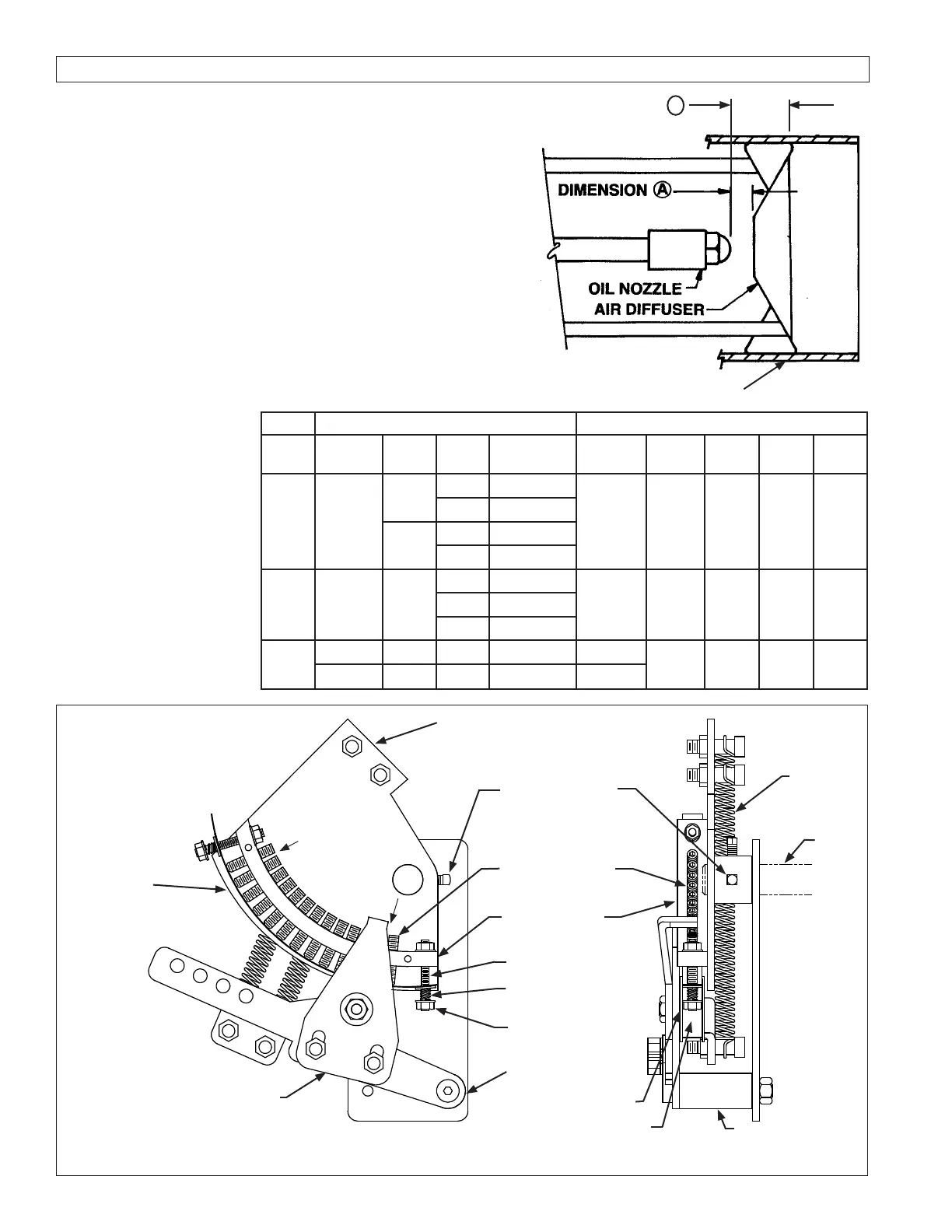
1. Oil nozzle position
The oil nozzle initial position is shown in Figure
G-2. The oil nozzle will be adjusted at start-up
and may be moved in or out from this initial set-
ting. In some cases, the oil nozzle may be inside
the diffuser
PRESSURE ATOMIZED NOZZLE AIR ATOMIZED NOZZLE
Model Diffuser
I.D.
Qty. Spray
Angle
Dimension
Inches
Diffuser
I.D.
Nozzle
Type
Spray
Angle
Dim.
A
Dim.
B
JB1
1 1/2”
2
30 3/8
NA NA NA NA NA
45 1/4
1
30 7/8
45 3/4
JB2
1 3/4” 2
30 3/4
2”
Single
Port
60
o
1/4” NA45 5/8
60 1/2
JB3
2 1/2” 3 60 5/8 2 1/2
Multi
Port
80
o
NA 3/8
2 7/8” 3 60 5/8 2 7/8
INNER FIRE CYLINDER
B
Figure G-1
Oil Nozzle Position,
Gas Pilot
Chart G-2
Flexible Strip
Cam
Cam Set Screws
Adjusting Screws
Aluminum Strip
End Screws
Spring
End Screw
Adjusting Nut
Cam Follower
Retention
Plate
Roller Washers
Roller
Cam Follower
Return
Springs
Jack
Shaft
Figure G-3
Fuel Cam Adjustment
High Fire
Position
Low Fire Position
 Loading...
