H. IGNITION SYSTEMS
Page 30 Ignition SystemsJB Manual
1. Gas Pilot Assembly
A crucial part of reliable burner operation is a dependable
pilot, which must be properly adjusted and kept clean. A gas
pilot is standard for all models except JB1 through JB2-20
straight oil pressure atomizing burners which have direct
spark ignition as standard. The following illustrations show
the typical confi guration and nominal adjustment parame-
ters of each pilot.
Figure H-1 showns the JB1 & JB2 gas pilot. Figure H-2
shows the JB3 gas pilot. Figure H-3 shows how the pilots
are positioned in the burner drawer.
Pilot gas pressure should be measured at the 1/8” port locat-
ed on the downstream side of the last pilot solenoid valve.
2. Oil Nozzle Positiion, Direct Spark Oil.
Figures H-5 and H-6 show the position of direct spark igni-
tion and nozzle positions. These are initial settings and will
be adjusted at start-up.
3. Air Damper Position
On a straight gas burner, the air damper should be open
about 1/4” at low fi re and close to full open at high fi re. In
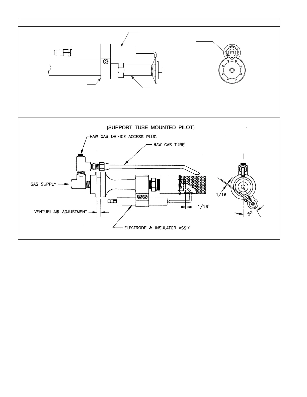
Figure H-2 JB3 PILOT ASSEMBLY
Natural Gas Pressure;
4 - 6” wc
LP Gas Pressure;
1.5 - 2.5” wc
some applications, the pilot requires an orifi ce in the pilot
gas supply line. With the exception of the JB3, this ori-
fi ce is located external of the blower housing.
The pilot to diffuser dimension is the distance of the face
of the pilot to the outer diameter of the diffuser.
For an oil or combination burner, the air damper should
be open about 3/8” at low fi re and close to full open at
high fi re.
4. Gas Modualting Control Valve Position
The gas valve should be open about 10% at low fi re and
stroked to abput 60% open at high fi re.
5. Oil Modulatining Control Valve Position.
For pressure atomizing, the low fi re position should be
adjusted to get the correct low fi re presure, as stated
on the rating label. Typically, this would be 100 psi for
simplex systems and 65 psi for return fl ow nozzles. The
high fi re position should be about 45
o
to 60
o
travel from
low fi re.
For air atomizing, the low fi re should be on about #2 po-
sition and the high fi re should be about the #8 position.
Electrode
Pilot
Electrode Clamp
Figure H-1
JB1 & JB2 Gas Pilot
Spark
Gap = 1/16”
Note: Required 2 1/2” - 3” wc
pressure for natural gas ans 1/2”
- 2” for LP, as measured at the
last solenoid in the pilot train.
 Loading...
