10
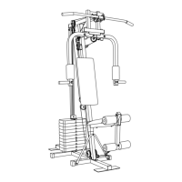
18. Route the Low Cable (70) on the indicated side of
the “V” Brace (42). Route the Low Cable into the
groove in a 3 1/2” Thin Pulley (4). Attach th
ePulley an d a Cable Trap (69) to the LArge Pivot
Bracket (52) with a 3/8” x 1 3/4” Bolt (68) and a
3/8” Jam Nut (82). Be sure the Cable Trap is in
the 1 o’clock position.
19. Attach a “U” Bracket (31) to one of the Press
Arms (29) with a 3/8” x 2 1/2” Bolt (44), a 3/8”
Flat Washer (65), and a 3/8” Nylon Locknut (2).
Be sure that the Cable Trap (69) is on the side
shown.
Attach the other “U” Bracket (31) to the other
Press Arm (29) in the same manner.
20. Lubricate a 5/16” x 2 1/4” Bolt (80). Attach a Small
Pivot Bracket (32) to the indicated “U” Bracket
(31) with the Bolt and a 5/16” Nylon Locknut (1).
Do not overtighten the Nylon; the Small Pivot
Bracket must be able to pivot freely.
Route the Low Cable (70) up around a 3 1/2” Thin
Pulley (4). Attach the Pulley and a Cable Trap
(69) to the Small Pivot Bracket (32) with a 3/8” x
1 3/4” Bolt (68) and a 3/8” Jam Nut (82). Be sure
the Cable Trap is in the 3 o’clock position.
20
31
29
29
65
65
44
44
31
2
2
32
31
1
68
11
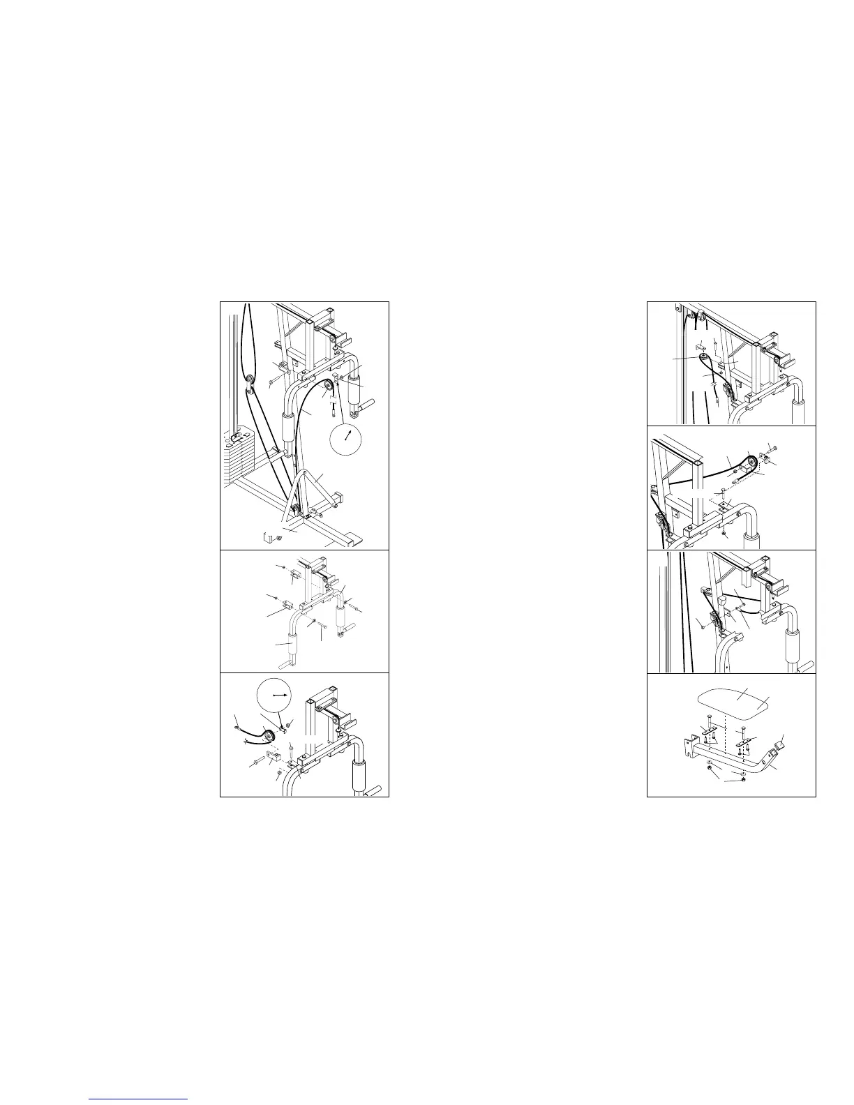
21. Wrap the Low Cable (70) around the 3 1/2” “V”
Pulley (74). Attach the Pulley and a Large Cable
Trap (73) to the indicated bracket on the Main
Upright (41) with a 3/8” x 2 1/4” Bolt (78) and a
3/8” Jam Nut (82). The Cable Trap must be
inside the bracket, and must be secured in the
position shown.
22. Lubricate a 5/16” x 2 1/4” Bolt (80). Attach the
Small Pivot Bracket (32) to tthe indicated “U”
Bracket (31) with the Bolt and a 5/16” Nylon
Locknut (1). Do not overtighten the Nylon
Locknut; the Small Pivot Bracket must be able
to pivot freely.
Route the Low Cable (70) up around a 3 1/2” Thin
Pulley (4). Attach the Pulley and the Cabel Trap
(69) to the Small Pivot Bracket (32) with a 3/8” x
1 3/4” Bolt (68) and a 3/8” Jam Nut (82). Be sure
the Cable Trap is in the indicated position.
23. Attach the Low Cable (70) to the indicated brack-
et on the Main Upright (41) with a 5/16” x 3/4”
Bolt (76) and a 5/16” Nylon Locknut (1). Do not
overtighten the Nylon Locknut; the Cable
must be able to swivel freely.
24. Press a 1 1/2” Inner Cap (19) into the Seat Frame
(18).
Insert a 1/4” x 2 1/4” Carriage Bolt (12) into the
centre hole of each Seat Bracket (13).
Attach each Seat Bracket (13) to the Seat (17)
with two 1/4” x 1/2” Screws (11).
Insert the 1/4” x 2 1/4” Carriage Bolts (12) into the
Seat Frame (18). The wide end of the Seat (17)
must be facing the curved end of the Seat
Frame. Tighten two 1/4” Nylon Locknuts (3), with
the two 5/16” x 1 1/2” Fender Washers (28), onto
the Carriage Bolts.
1
41
70
76
17
Wide End
18
3
12
11
11
13
13
19
28
82
31
1
80–Lubricate
70
69
32
4
68
22
23
24
41
73
74
70
78
82
21
42
70
69
82
80–Lubricate
4
 Loading...