ELECTRICAL CONNECTIONS
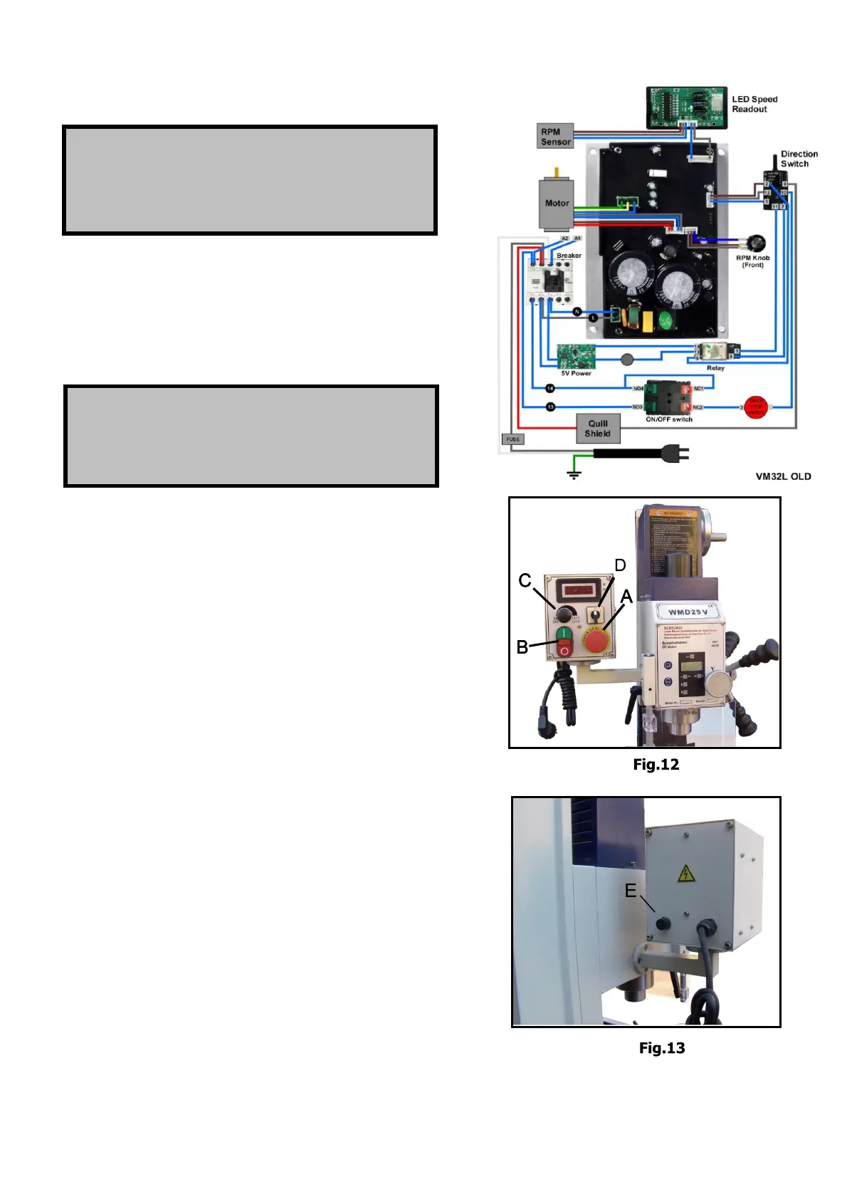
Emergency stop switch (A,Fig. 12 )has the function of
emergency stopping and the protective function to the
machine and electric components.
On/off Switch (B,Fig.12) Green push button marked
“I” to start the motor, Red push button marked “O” to
switch the motor off.
Speed control knob (C,Fig. 12) turn it clockwise to
increase the spindle speed, reverse to decrease. The
knob should be turned to zero each time the machine
is stopped. Always start the machine with the knob
is stopped. Always start the machine with the knob
set at zero.
F/R switch(D, Fig.12)changing the postion of switch
Will reverse the direction of the motor. F-forward
Direction, R- reverse direction.
Fuse Base (E, Fig. 13) Located on the back plate of
electrical box. Fuse what rate is 10A is put in the base.
Turn counter-clockwise the button to open and
Change the fuse, reverse to retighten
WARNING!
A qualified electrician must make all electrical
connection
s!
Failure to do so may cause serious injury!
Before connecting the machine to the mains, make sure
that the el
ectrical values of the mains supply are the
same as those for the machine
’s electrical components.
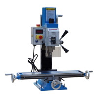
Use the wiri
ng diagram (Fig. 11) for connecting the lathe
to the mains suppl
y.
WARNING!
Make sure the machine is properly ground!
Failur
e
to do so may cause serious in
jury and
damage t
o user!
DC-Motor - its type is ,
Make sure that all
2 phase (L, N) are connected.
Defective or incorrect connection will render the
guar
antee null and void.
Indicators are:
Motor runs hot immediately (3-4 minutes).
Motor doesn’t run silently and has no power.
- 9 -
110V 1100W
 Loading...