COMMISSIONING
6 720 815 725 (2015/05)34
5.5.1 CHECKING THE GAS INLET PRESSURE
The inlet pressure to the appliance must be checked using the following
procedure:
MEASURING THE INLET PRESSURE
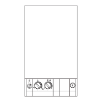
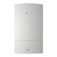
Fig. 53 Inlet pressure test point
▶ Close gas isolation valve.
▶ Slacken the screw in the inlet pressure test point a quarter turn and
connect a manometer.
▶ Open gas isolation valve.
▶ Measure the pressure with the boiler running at maximum.
– Press the Performance test button (J) for more than ten seconds
and set Central Heating temperature to maximum.
– The Performance test button (J) will illuminate continually and the
display (C) will alternate between and the central heating flow
temperature.
▶ Check the gas supply working pressure at the gas valve conforms to
values shown in Fig. 54 or Fig. 55 .
▶ If pressure is satisfactory press the Performance test button (J) again
and the boiler will return to normal operation.
▶ If left in the Performance test mode the control will return to normal
operation after 15 minutes.
▶ Close the gas isolation valve and remove the manometer.
▶ Re-seal the screw in the gas inlet pressure test point.
▶ Open the gas isolation valve and check for gas tightness.
GAS PRESSURE WITHIN THE SYSTEM
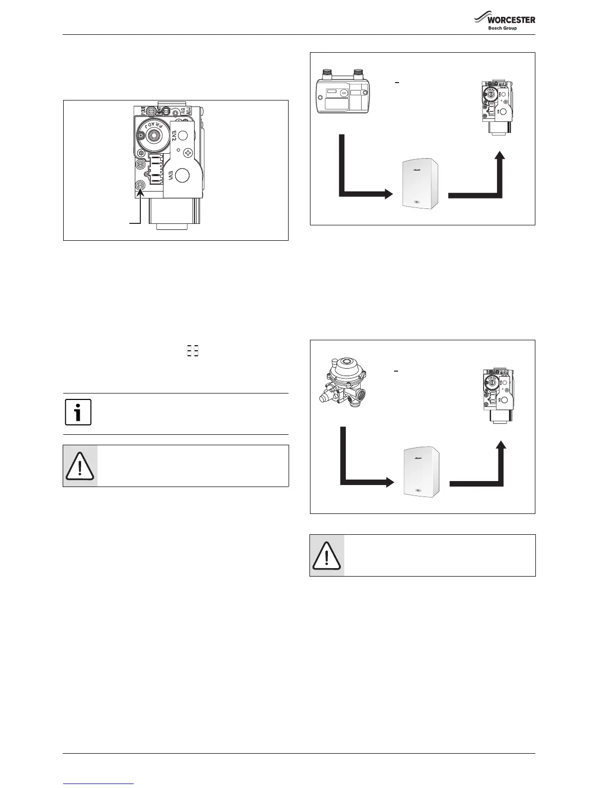
Refer to the figure below for natural gas pressures.
The pressure at the boiler must not be less than the pressure read at the
meter minus 1 mbar.
The pressure drop from the meter to the gas valve must not be more than
2.5 mbar for natural gas.
If the pressure drops are greater than shown in figure 54, then this
would indicate a problem with the pipe work or connections within the
system.
Fig. 54 Natural gas pressures
Refer to the figure below for L.P.G gas pressures.
The pressure at the boiler must not be less than the pressure read at the
meter minus 2.5 mbar.
The pressure drop from the meter to the gas valve must not be more than
4 mbar for LPG.
If the pressure drops are greater than shown in figure 55, then this
would indicate a problem with the pipe work or connections within the
system.
Fig. 55 L.P.G. pressures
Ensure inlet pressure is satisfactory with all other gas
appliances working.
NOTICE: Do not continue commissioning until the
correct gas inlet pressure is achieved.
Inlet pressure
test point
6720647361-58.1Wo
NOTICE:
Do not continue commissioning until the correct gas
pressure is achieved.
Meter
Boiler inlet
Gas Control
valve
19 - 23 mbar
18 - 22 mbar
16.5 - 20.5 mbar
1 mbar
drop
1.5 mbar
drop
Natural Gas
< 2.5mbar
difference
6720644744-44.2Wo
Gas Control
valve
L.P.G.
< 4.0mbar
difference
Regulator
Boiler inlet
32 - 45 mbar
29.5 - 42.5 mbar
28 - 41 mbar
2.5 mbar
drop
1.5 mbar
drop
6720644744-45.2Wo
 Loading...