Fan installation
Wet Rooms: on/o switch must be
situated so that it cannot be touched
by persons making use of the bath or shower.
A means for disconnection in all poles must be
incorporated in the fixed wiring in accordance
with wiring regulations.
Ť ,IPHWDOVZLWFKER[HVDUHXVHGHDUWKLQJ
UHJXODWLRQVPXVWEHIROORZHG
Ť 7KHFURVVVHFWLRQDODUHDRIWKHVXSSO\FRUG
XVHGVKRXOGEHUDQJHGEHWZHHQPPŸ
Ť 9;9;9;ŢFRUH
9;79;79;7ŢFRUH
Ť 9;79;79;7$ZDOORU
FHLOLQJRQRijVZLWFKZLWKLQGLFDWRUOLJKW
LVUHFRPPHQGHG
Step 1
&KHFNWKDWWKHHOHFWULFDOUDWLQJVKRZQRQ
WKHIDQPDWFKHV\RXUPDLQVVXSSO\
Step 2
&KHFNWKHUHDUHQREXULHGSLSHVRUFDEOHV
HJHOHFWULFLW\JDVZDWHUEHKLQGWKHVZLWFK
location (in the wall or above the ceiling).
,ILQGRXEWVHHNSURIHVVLRQDODGYLFH
Step 3
,VRODWHWKHPDLQVVXSSO\
Step 4
,QVWDOOWKHLVRODWLQJVZLWFKDQG
RQRijVZLWFKLIUHTXLUHG
Step 5
/D\LQWKHFDEOHIURPWKHLVRODWLQJVZLWFK
WRWKHIDQORFDWLRQYLDWKHRQRij
VZLWFKLIUHTXLUHG
Step 6
/D\LQWKHFDEOHIURPWKHLVRODWLQJ
switch to the point of connection to
WKHPDLQVVXSSO\
Warning: Do not make any connections
to the electrical supply at this stage.
Step 7
Make all connections within the isolating
VZLWFKDQGWKHRQRijVZLWFKLIUHTXLUHG
Step 1 – Preparing the fan
for installation
Ť 8QGRWKHHOHFWULFDOFRYHUVFUHZDQGUHPRYH
the electrical cover.
If working above ground floor level, safety
precautions must be observed.
If installing in a ceiling, appropriate
termination ancillaries are required
Step 2 – Mount the fan body
Ť ,IZDOOPRXQWLQJHQVXUHIDQERG\LV
RULHQWDWHGKRUL]RQWDOO\see F.
Step 3 – Wire the electrical
connections
Ť 0DNHVXUHPDLQVVXSSO\LVLVRODWHG6ZLWFKRij
WKHPDLQVHOHFWULFDOVXSSO\DQGUHPRYHIXVHV
Ť 3OHDVHHQVXUH\RXIROORZWKHULJKWGLDJUDP
DQGLQVWDOODWLRQW\SHIRUWKHPRGHO\RXKDYH
SXUFKDVHGsee I.
Ť 8VHFDEOHFODPSWRVHFXUHFDEOH
Fan settings
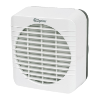
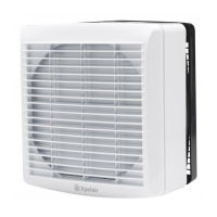
VX100T / VX120T / VX150T
Ť 7RDGMXVWWKHRYHUUXQsee J. For location of
WKHWLPHUFRQWUROsee K.
Ť 2SHUDWHWKHIDQXVLQJRQRijVZLWFKQRW
SURYLGHG:KHQVZLWFKLVRijIDQRSHUDWHV
IRUWKHVHWWLPHGHOD\
VX100 / VX120 / VX150
Ť 2SHUDWHIDQXVLQJRQRijVZLWFK
QRWVXSSOLHG
Finally refit the electrical cover ‘O’ ring seals
(where applicable) and screw in place.
D
E
H
G
I
J
Installing switches and cables
08
 Loading...