10
Alignment Preparation & Precautions
A 50-Ohm RF load and in-line wattmeter must be
connected to the antenna jack in all procedures that
call for transmission; alignment is not possible with
an antenna. After completing one step, read the next
step to see if the same test equipment is required. If
not, remove the test equipment (except dummy load
and wattmeter, if connected) before proceeding.
Correct alignment requires that the ambient tem-
perature be the same as that of the transceiver and
test equipment, and that this temperature be held
constant between 68 °F ~ 86 °F (20 °C ~ 30 °C). When
the transceiver is brought into the shop from hot or
cold air, it should be allowed some time to come to
room temperature before alignment. Whenever pos-
sible, alignments should be made with oscillator
shields and circuit boards firmly affixed in place.
Also, the test equipment must be thoroughly
warmed up before beginning.
Note: Signal levels in dB referred to in the alignment
procedure are based on 0dBµ = 0.5µV.
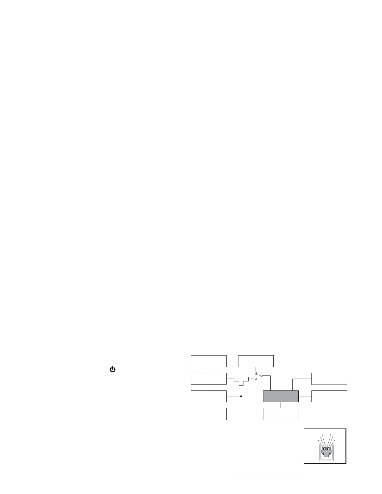
Test Setup
Set up the test equipment as shown below for trans-
ceiver alignment.
Entering the Alignment Mode
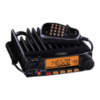
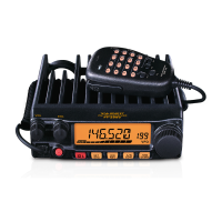
Alignment of the FT-2900R is performed using a front
panel software-based procedure. To perform align-
ment of the transceiver, it must first be placed in the
“Alignment Mode,” in which the adjustments will
be made and then stored into memory.
To enter the Alignment mode:
1. Press and hold in the
[
MHz
(
SET
)]
key while turning
the radio on.
2. Press and hold in the
[
PWR
( )]
switch for 1/2 sec-
ond to turn the radio off.
3. To enter the Alignment mode, press and hold in the
[REV(DW)] and [D/MR(MW)] keys while turning the
radio on. Once the radio is on, release these two key.
The transceiver is now in the “Alignment Mode.”
PLL Reference Frequency
Rotate the DIAL knob to set the alignment param-
eter to “
B0201 rFB0201 rF
B0201 rFB0201 rF
B0201 rF.”
Press the
[
D/MR
(
MW
)]
key to enable adjustment
of the “PLL Reference Frequency.”
Press the PTT switch to activate the transmitter,
adjust the DIAL knob so that the counter fre-
quency reading is 146.000 MHz (±80 Hz).
Press the
[
D/MR
(
MW
)]
key.
RF Front-end Tuning
Inject a 145.100 MHz signal at a level of –10 dBµ
(with 1 kHz modulation @±3.5 kHz deviation)
from the RF signal generator.
Rotate the DIAL knob to set the alignment param-
eter to “
B0111 tnB0111 tn
B0111 tnB0111 tn
B0111 tn.”
Press the
[
D/MR
(
MW
)]
key to enable adjustment
of the “RF Front-end Tuning.”
Adjust the DIAL knob so that the maximum
SINAD.
Press the
[
D/MR
(
MW
)]
key.
Squelch Threshold Level
Inject a 145.100 MHz signal at a level of –14 dBµ
(with 1 kHz modulation @±3.5 kHz deviation)
from the RF signal generator.
Rotate the SQL knob to the 10-o’clocl position.
Rotate the DIAL knob to set the alignment param-
eter to “
B0111 tLB0111 tL
B0111 tLB0111 tL
B0111 tL.”
Press the
[
D/MR
(
MW
)]
key to enable adjustment
of the “Squelch Threshold Level.”
Press the
[
D/MR
(
MW
)]
key three times.
Press the
[
D/MR
(
MW
)]
key.
Alignment
TEST EQUIPMENT SETUP
MIC SW2
MIC SW1
GND +8V
MIC INPUT
PTT/CLONE
FT-2900R
Inline
Wattmeter
SINAD MeterDeviation Meter
Frequency
Counter
RF
Signal Generator
AF
Signal Generator
RF
Signal Generator
50-Ohm
Dummy Load
MIC
ANT
EXT SP
RF Sampling
Coupler
DC INPUT
 Loading...