69
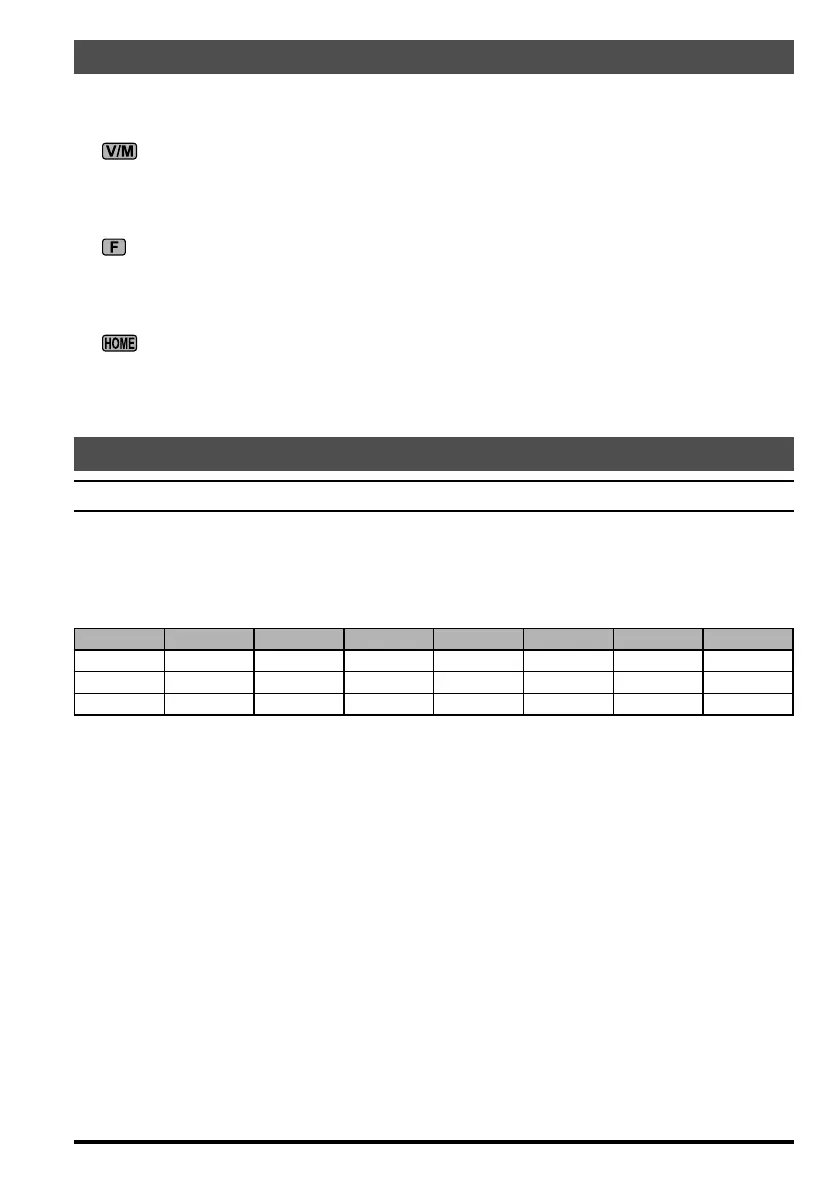
Power-on Microprocessor Reset Procedure
Some or all transceiver settings can be reset to their factory-default states using one of the
following power-on routines:
+ POWER on: Reset all memories and following menu setting to factory-default.
Menu #06 (AM STEP), 23 (DCS CODE), 30 (FM STEP), 35 (MEM TAG), 42 (RPT
SHIFT), 47 (SSB STEP), and 48 (TONE FREQ).
+ POWER on: Reset all menu setting (except following menu) to factory-default.
Menu #06 (AM STEP), 23 (DCS CODE), 30 (FM STEP), 35 (MEM TAG), 42 (RPT
SHIFT), 47 (SSB STEP), and 48 (TONE FREQ).
+ POWER on: CPU master reset for all memories and menu setting.
Some menu mode items are not initialized unless turn the power switchoff and on
after having performed “Menu Mode Reset” or “All Reset”.
Appendix
BAND DATA FORMAT
The FT-818 BAND DATA Format (available on the ACC jack) is presented below. The
BAND DATA line provides a stepped voltage, which denotes the current operating band.
This data may be interpreted by an external device (such as an antenna switch or ampli-
er)to provide automatic band switching.
BAND LEVEL BAND LEVEL BAND LEVEL BAND LEVEL
1.8 MHz 0.33 V 10 MHz 1.33 V 21 MHz 2.33 V 50 MHz 3.33 V
3.5 MHz 0.67 V 14 MHz 1.67 V 24.5 MHz 2.67 V 144 MHz 3.67 V
7 MHz 1.00 V 18 MHz 2.00 V 28 MHz 3.00 V 430 MHz 4.00 V
Use shielded cable for interconnections to external devices, so as to prevent RF interfer-
ence.
 Loading...