81
E
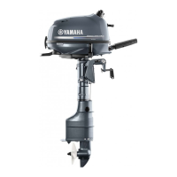
9. Connect:
• Wiring harness coupler 1
• Warning indicator coupler 2
• Variable trolling RPM switch coupler 3
• Route the wiring harness a, warning indica-
tor lead b, neutral switch lead c, and vari-
able trolling RPM switch lead d as shown.
• Fasten the battery cable e, wiring harness,
variable trolling RPM switch lead, warning
indicator lead, and neutral switch lead with a
plastic tie f as shown.
• Fasten the wiring harness, warning indicator
lead, and neutral switch lead with clamp g
as shown.
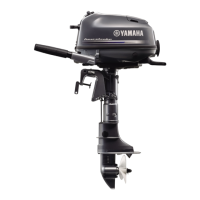
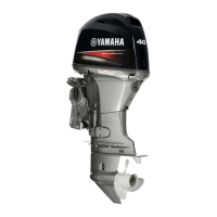
10. Fasten:
• Plastic tie 1
Fasten the battery cable, wiring harness, warn-
ing indicator lead and variable trolling RPM
switch lead to the shift cable and throttle cable.
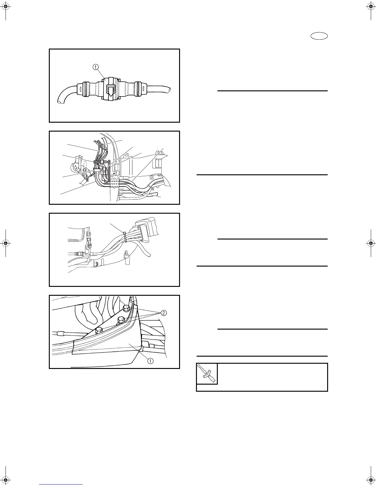
11. Install:
• Fitting plate 1
•Bolts 2
After secure the fitting plate, lift the tiller handle
straight up and check that the cables and wires
are not stretched.
Bolt:
10.0 N • m
(1.02 kgf • m, 7.4 ft • lb)
TillerHandle.book Page 81 Friday, April 12, 2013 3:19 PM

 Loading...