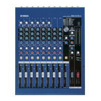
MG12/4FX
34
3.13 Residual Noise
In the state 3.1, set the all Fader and Level Control of all input CH to MIN and set the all Assign switch to OFF.
Then, the noise level shall be less than the level specified in the Table 3.13-1.
* In measuring the C-R OUT and the PHONES, set the ST Fader to MIN.
* Set the ST fader at MIN when measuring C-R OUT and PHONES.
(Use a 12.7 kHz, -6 dB/octave low pass filter when measuring noise.)
3.14 PHANTOM
Connect a 10k ohms load resistance between the pin 1 and 2 of the MIC and short-circuit between the pin 2 and 3.
Turn on the PHANTOM switch (LED shall light) and the voltage between pin 1 and 2 shall be within +35 ±3V.
3.15 DIGITAL EFFECT
Set the CH1 and MASTER as follows and feed -40dBu signal to CH1 MIC.
When setting EFFECT RTN fader and EFFECT RTN AUX VR to MAX, the output level shall be within the range specified
the Table 3.15-1.
*** CH1 ***
GAIN VR, AUX VR: MIN
Fader, EFFECT VR: MAX
ON, PFL switch: OFF
Feed no signal and set the CH EFFECT level control and CH LEVEL VR to MIN.
The noise level of “ST OUT L/R” shall be less than -50dBu.
Feed music source and check the DIGITAL EFFECT by listening to it.
4.16 Preparation of delivery
EQ Gain control : CENTER
PAN, BAL, PAN/BAL control : CENTER
Other VR control : MIN
FADER : MIN
Lock-PUSH switch : OFF
ON/STANDBY switch : STANDBY
Table3.13-1[dBu]
Fader/VR STEREOOUT GROUPOUT AUXSEND EFFECTSEND C-ROUT
MAX -78.0 -80.0 -75.0 -75.0 -72.0
MIN -100.0 -100.0 -100.0 -100.0 -87.0
Table3.15-1[dBu]
OUTPUT
EFFECTRTNPFL
STfader
AUXsendVR
C-R/PHONESVR
PROGRAMselect
switch
PARAMETER OUTPUTleve
STLOUT
STROUT
over0dB
AUX
OFF
over-4dB
C-RL
C-RR
ON
MAX 1 MIN
over-10dB
w
w
w
.
x
i
a
o
y
u
1
6
3
.
c
o
m
Q
Q
3
7
6
3
1
5
1
5
0
9
9
2
8
9
4
2
9
8
T
E
L
1
3
9
4
2
2
9
6
5
1
3
9
9
2
8
9
4
2
9
8
0
5
1
5
1
3
6
7
3
Q
Q
TEL 13942296513 QQ 376315150 892498299
TEL 13942296513 QQ 376315150 892498299
http://www.xiaoyu163.com
http://www.xiaoyu163.com

 Loading...