Instrument and control functions
6-47
6
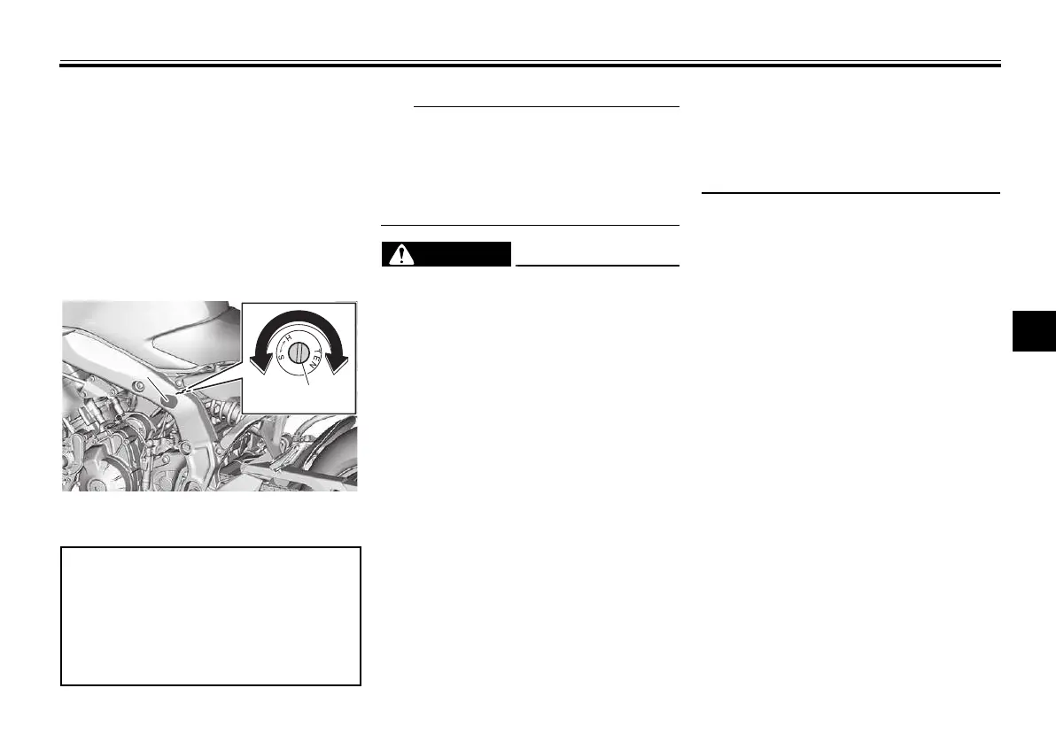
2. Turn the adjusting screw in direc-
tion (a) to increase the rebound
damping force.
Turn the adjusting screw in direc-
tion (b) to decrease the rebound
damping force.
To set the rebound damping
force, turn the adjuster in direction
(a) until it stops, and then count
the turns in direction (b).
When turning the damping force ad-
juster in direction (b), it may turn be-
yond the stated specifications,
however such adjustments are ineffec-
tive and may damage the suspension.
EWA10222
This shock absorber assembly con-
tains highly pressurized nitrogen
gas. Read and understand the fol-
lowing information before handling
the shock absorber assembly.
Do not tamper with or attempt
to open the cylinder assembly.
Do not subject the shock ab-
sorber assembly to an open
flame or other high heat source.
This may cause the unit to ex-
plode due to excessive gas
pressure.
Do not deform or damage the
cylinder in any way. Cylinder
damage will result in poor
damping performance.
Do not dispose of a damaged or
worn-out shock absorber as-
sembly
yourself. Take the shock
absorber assembly to a Yamaha
dealer for any service.
1. Cap
2. Rebound damping force adjusting screw
Rebound damping setting:
Minimum (soft):
2 1/2 turn(s) in direction (b)
Standard:
1 turn(s) in direction (b)
Maximum (hard):
0 turn(s) in direction (b)
UBMEE0E0.book Page 47 Thursday, March 7, 2024 10:23 AM

 Loading...