10
DISASSEMBLY PROCEDURE
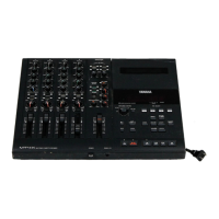
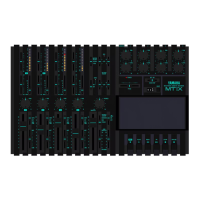
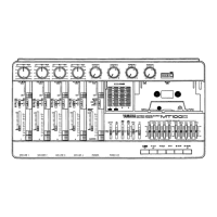
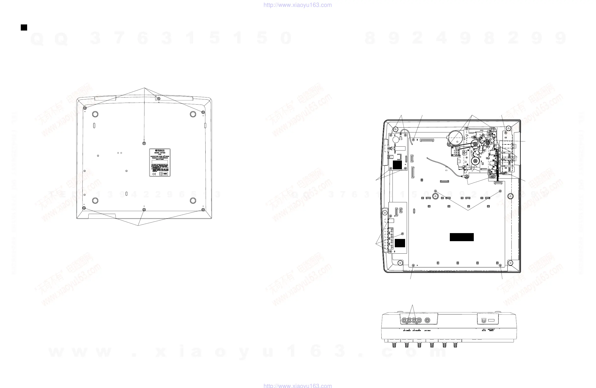
Fig.1
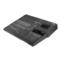
MT400
[320]: Bind Head Tapping Screw-P 3X10 MFZN2BL (EP630660)
[320]
[320]
1. Lower Case
1-1 Remove the seven (7) screws marked [320]. The
lower case can then be removed. (Fig.1)
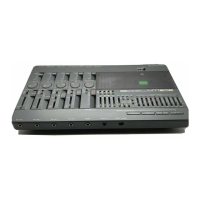
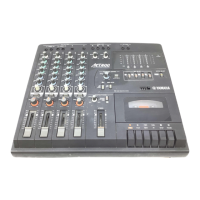
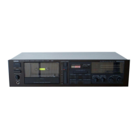
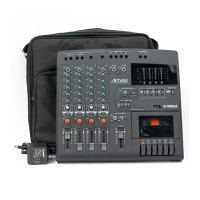
4. SUB 2/3, 3/3 Circuit Boards
4-1 Remove the lower case. (See Procedure 1.)
4-2 Remove the three (3) screws marked [320d] and
the two (2) screws marked [320e].
The SUB2/3 circuit board can then be removed.
(Fig.2, Fig.3)
4-3 Remove the four (4) screws marked [320f]. The SUB
3/3 circuit board can then be removed. (Fig.2)
2. Cassette Mechanism
2-1 Remove the lower case. (See Procedure 1.)
2-2 Remove the five (5) screws marked [320a]. The
cassette mechanism can then be removed. (Fig. 2)
3. REC 1/2, 2/2 Circuit Boards
3-1 Remove the lower case. (See Procedure 1.)
3-2 Remove the cassette mechanism. (See Procedure 2.)
3-3 Remove the six (6) screws marked [320b]. The REC
1/2 circuit board can then be removed. (Fig.2)
3-4 Remove the two (2) screws marked [320c]. The REC
2/2 circuit board can then be removed. (Fig.2)
[320e]
[320f] [320b] [320a] [320c]
[320b]
[320c]
[320a]
[320b]
[320b]
[320b]
[320f]
[320d]
REC 1/2
SUB
2/3
SUB
3/3
Fig.2
Fig.3
〈
REAR
〉
〈
FRONT
〉
〈
REAR
〉 〈
FRONT
〉
〈
Bottom
〉
〈
Top
〉
w
w
w
.
x
i
a
o
y
u
1
6
3
.
c
o
m
Q
Q
3
7
6
3
1
5
1
5
0
9
9
2
8
9
4
2
9
8
T
E
L
1
3
9
4
2
2
9
6
5
1
3
9
9
2
8
9
4
2
9
8
0
5
1
5
1
3
6
7
3
Q
Q
TEL 13942296513 QQ 376315150 892498299
TEL 13942296513 QQ 376315150 892498299
http://www.xiaoyu163.com
http://www.xiaoyu163.com
 Loading...