11
Fig.4
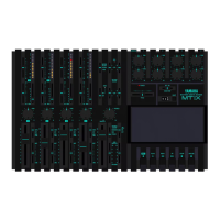
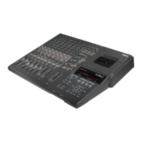
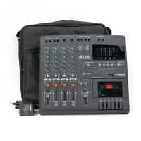
MT400
11A
2
3
4
5
6
7
1Y
2A
2Y
3A
3Y
V
SS
8
9
10
11
12
13
14
V
DD
6A
6Y
5A
5Y
4A
4Y
TC4069UBP
(
IG001720
)
Hex Inverter
1Input (Output)1
2
3
4
5
6
7
Output (Input)1
Output (Input)2
Input (Output)2
Control2
Control3
V
SS
8
9
10
11
12
13
14
V
DD
Control1
Control4
Input (Output)4
Output (Input)4
Output (Input)3
Input (Output)3
TC4066BP
(
IX631591
)
Quad Bilateral Swich
BA7755A
(
XH519A00
)
Head Switcher
BA6137
(
XA534A00
)
LED Driver
AN6292NK
(
XJ637A00
)
Dual dbx NR
NJM2068LD
(
XM356A00
)
NJM4558L
(I
X614610
)
M5216L
(
XB419A00
)
M5218AL
(
XH471A00
)
Dual Operational Amplifier
1
A
2 3 4 5 6 7 8
IN V
+IN
OUT
AAA
+VIN
+IN
OUT
BBB
+
B
+
1 2 3 4 5
VCC SW GND CTRL1CTRL2
D1
+ + + + +
+
Constant
Current
Circuit
1
D2
2
D3
3
D4
4
GND
5
D5
6
Amp
Output
7
IN
8
V
CC
9
3
8
9
20
21
26
ENPHASIS
BAND PASS FILTER IN
REC OUT
1
28
GND
+
2
27
R/P IN R/P IN
ENPHASIS
4
LINE OUT LINE OUT
5
24
ENPHASIS ENPHASIS
6
23
CCA-A OUT CCA-A OUT
7
22
CCA-B IN CCA-B IN
BAND PASS FILTER IN
REC OUT
10
19
BAND PASS FILTER OUT BAND PASS FILTER OUT
11
13
1618
LEVEL SENSOR IN
TIMING CURRENT ADJ.
LEVEL SENSOR IN
12
17
TIMING CAP. TIMING CAP.
DECODE / ENCODE SW
14
15
SW
B CH.
A CH.
+
DE
OFF
LINE AMP.
OFF
EN ENDE
+
+
+
DE
OFF
BUFFER
EN
EN
OFF OFF
DE DEEN
+
EN
CCA-B
CCA-A
REC OUT
AMP.
OFF
LEVEL SENSOR
OFF
DE DEEN
+
+
EN PHASIS
AMP.
25
IC BLOCK DIAGRAM
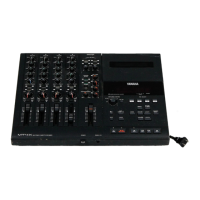
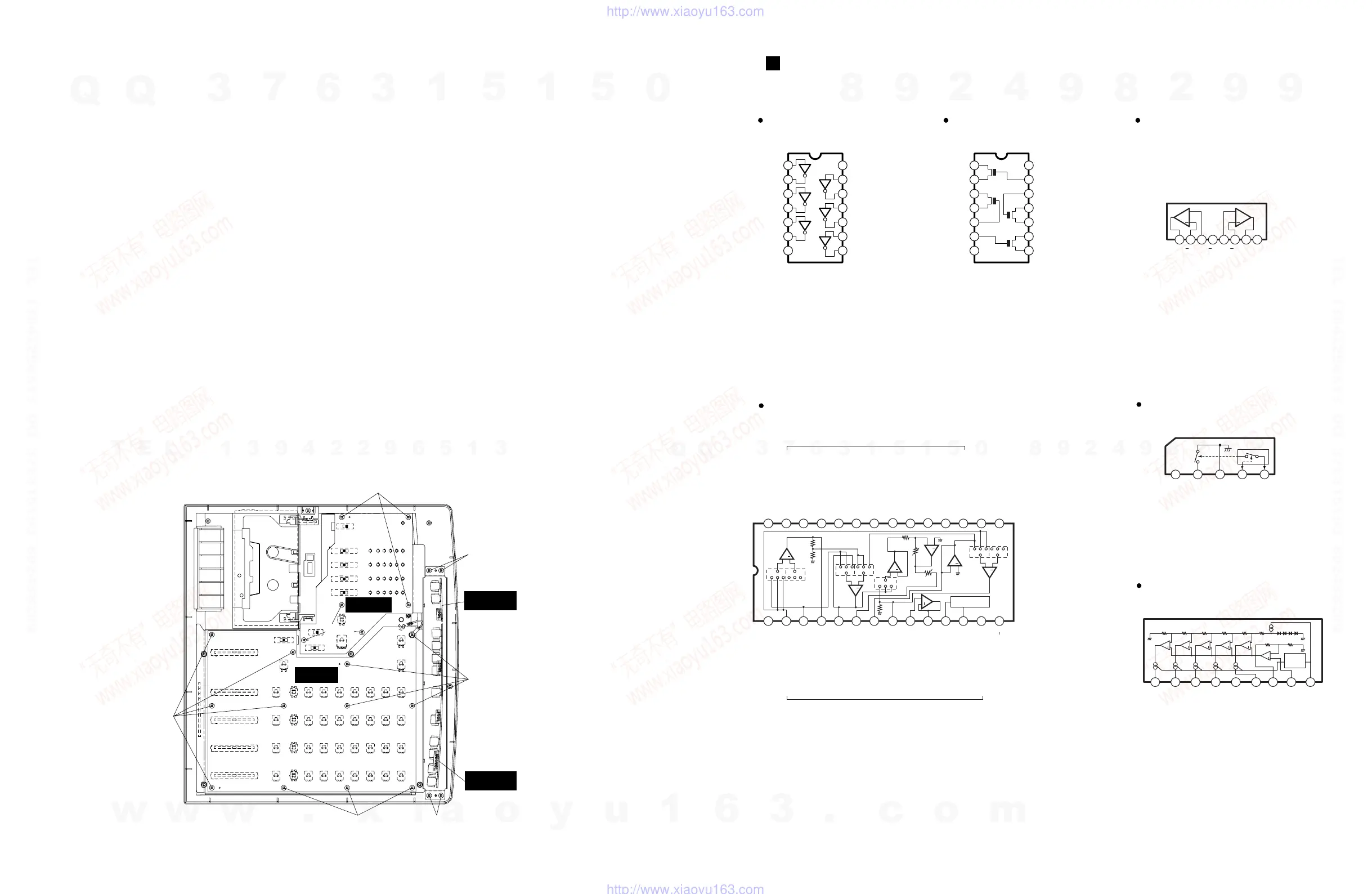
5. SUB 1/3 Circuit Board
5-1 Remove the lower case. (See Procedure 1.)
5-2 Remove the PITCH knob of the TAPE SPEED
CONTROL on the upper case and the six (6) screws
marked [320g].
The SUB 1/3 circuit board can then be removed.
(Fig.4)
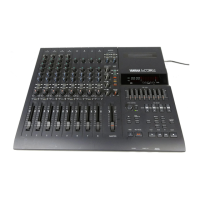
6. MIX 1/3 Circuit Board
6-1 Remove the lower case. (See Procedure 1.)
6-2 Remove the SUB 1/3 circuit board. (See Procedure 5.)
6-3 Remove the knob on the upper case and the twelve
(12) screws marked [320h].
The MIX 1/3 circuit board can then be removed.
(Fig.4)
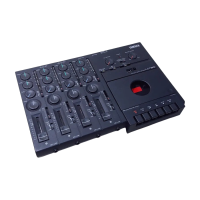
7. MIX 2/3, 3/3 Circuit Boards
7-1 Remove the lower case. (See Procedure 1.)
7-2 Remove the four (4) screws marked [320I] on the
plate. The plate with the MIX 2/3 and 3/3circuit
boards can then be removed. (Fig.4)
7-3 Remove the holding plate of each jack. The each
circuit board can then be removed.
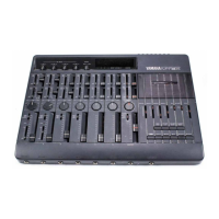
[320h]
[320h]
MIX 1/3
[320i]
MIX 2/3
[320h]
[320g]
SUB 1/3
[320g]
MIX 3/3
[320i]
〈
FRONT
〉
〈
REAR
〉
w
w
w
.
x
i
a
o
y
u
1
6
3
.
c
o
m
Q
Q
3
7
6
3
1
5
1
5
0
9
9
2
8
9
4
2
9
8
T
E
L
1
3
9
4
2
2
9
6
5
1
3
9
9
2
8
9
4
2
9
8
0
5
1
5
1
3
6
7
3
Q
Q
TEL 13942296513 QQ 376315150 892498299
TEL 13942296513 QQ 376315150 892498299
http://www.xiaoyu163.com
http://www.xiaoyu163.com
 Loading...