6
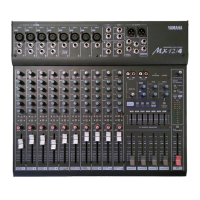
Front panel
MX12/4—Owner’s Manual
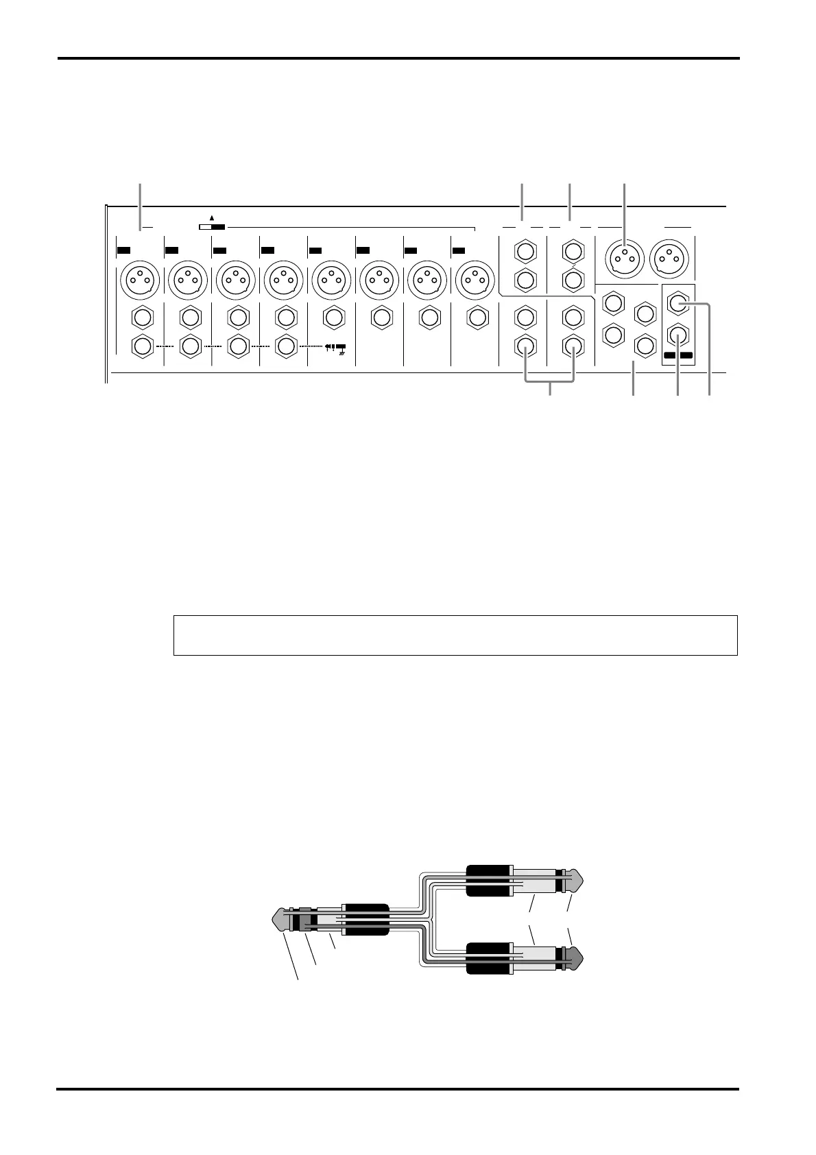
Connector section
1
INPUT
MIC (1~8)
—These are balanced XLR type mic input jacks (1: ground, 2: hot, 3: cold).
These inputs are compatible with 50~600
Ω
microphones.
LINE (1~8)
—These are balanced TRS phone type line input jacks (T: hot, R: cold, S:
ground).
These inputs are compatible with 600 ohm line level devices.
It is also possible to connect unbalanced phone plugs, but noise may enter the signal if the
cables are long or if the location is susceptible to electromagnetic interference.
INS I/O 1~4
—These are input/output jacks placed between the equalizer and fader of input
channels 1~4.
The nominal input level/impedance is 0dB/600
Ω
, and the nominal output level/impedance is
0dB/10k
Ω
.
Devices such as graphic equalizers, compressors or noise filters can be connected here.
The INS I/O jacks provide bi-directional connections using TRS (tip, ring, sleeve) phone
jacks. These connections require a special insertion cable such as shown in the following dia-
gram.
Note:
It is not possible to connect both the MIC INPUT jack and the LINE INPUT jack for
an individual input channel. Only one or the other jack may be used.
PHONES
L(MONO)
R
C-R OUT
ST OUTPUT
RTN SEND
GROUP
OUTPUTINPUT INPUT
L
(MONO)
R
L
(MONO)
R
EFFECT MONI
2
1
2
3
4
MONI
1
PHANTOM +48V
ON
MIC
INPUT INPUT INPUT INPUT INPUT INPUT INPUT INPUT
LINE LINELINE LINE LINE LINE LINE LINE
INS
I ⁄ O
INS
I ⁄ O
INS
I ⁄ O
INS
I ⁄ O
INSERT I/O
OUT IN
9
10
11
12
12345678
MIC
MIC
MIC
MIC
MIC
MIC MIC
L
R
OFF
2135
4687
to the input jack of
the external processor
to the output jack of
the external processor
to the INS I/O jack
Tip
Tip
Ring
Sleeve
Sleeve
 Loading...