RX-V620/HTR-5460/RX-V620RDS
RX-V620/HTR-5460
RX-V620RDS
8
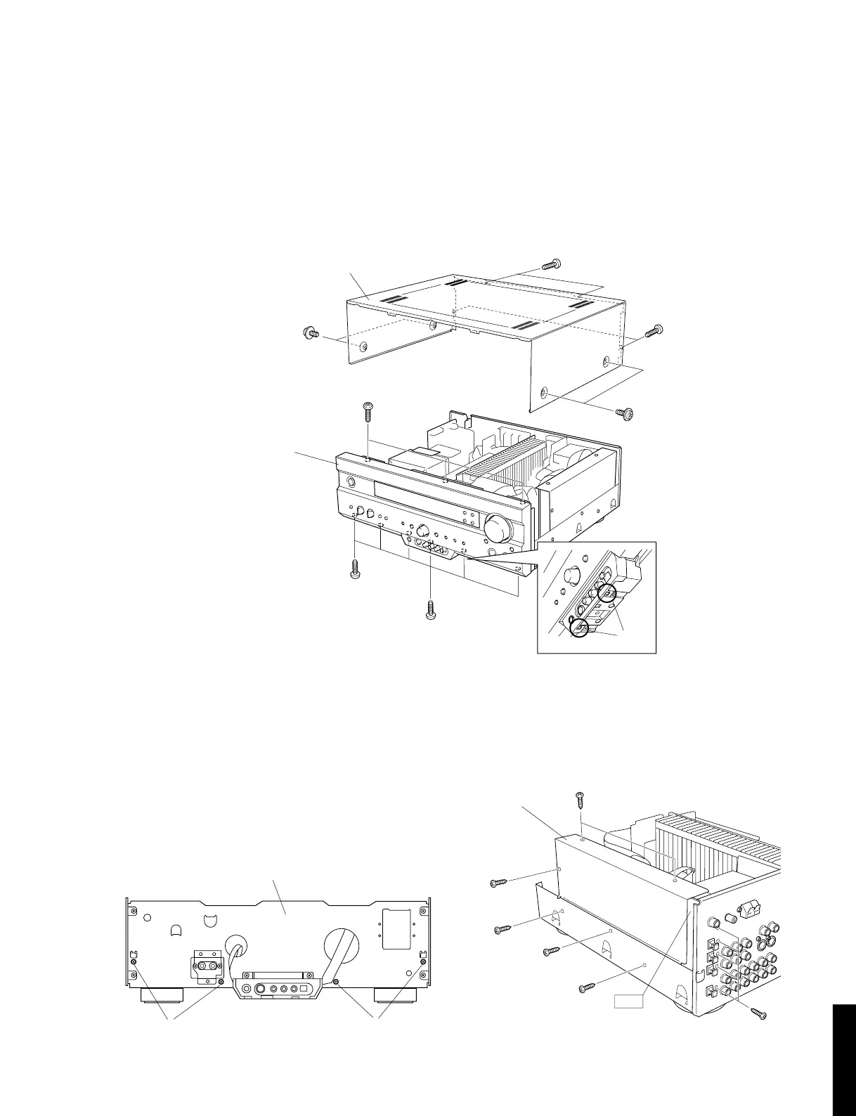
■ DISASSEMBLY PROCEDURES (Remove parts in the order as numbered.)
1. Removal of Top Cover
Remove 8 screws ( q and w ) and then remove the Top Cover in Fig. 1.
2. Removal of Front Panel Unit
a. Remove 9 screws ( e, r and t ) in Fig. 1.
b. Remove CB104, CB303 and ground wire.
c. Lift 2 hooks and then remove the Front Panel Unit in Fig. 1.
Fig. 1
Fig. 2
Fig.3
3. Removal of Sub Chassis Unit
Remove 4 screws ( y ) and then remove the Sub
Chassis Unit in Fig. 2.
4. Removal of DSP P.C.B.
a. Remove 4 screws ( u ) and then remove the Shield
Case Cover in Fig. 3.
b. Remove 7 screws ( i and o ) and then remove the
DSP P.C.B. in Fig. 3.
w
w
t
e
r
Front Panel Unit
Top Cover
q
q
u
y
y
Hooks
Sub Chassis Unit
u
i
u
i
o
Shield Case Cover
 Loading...